
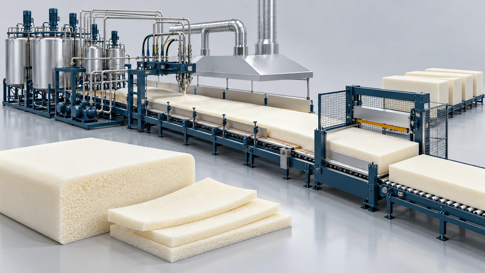
Continuous Slabstock Foaming Solution
Continuous Slabstock Foaming for flexible polyurethane foam, with a 13-component configuration integrating metering, dynamic mixing, recipe control, conveyor forming and cut-off.
Continuous Slabstock Foaming Plant Solutions
Continuous Slabstock Foaming meters and dynamically mixes polyurethane raw materials onto a moving forming conveyor. The reacting foam rises into a continuous bun for cut-off, curing and later slicing into furniture and mattress foam. The 13-component configuration described here supports up to 350 kg/min material output, 2–7 m/min line speed and a specified 5–80 kg/m³ density range, subject to formulation and operating conditions. The previously listed 6–12-stream equipment and 300 kg/min customer application remain separate reference configurations.
13 Material Circuits and Recipe Management
Dedicated bulk and minor-component storage and metering circuits support the selected formulation. The control system stores 100 recipes and supports online switching, with five PLC interfaces reserved for expansion.
Two Pouring Modes and Coordinated Forming
Oscillating-head and overflow-trough pouring feed an electrically adjustable drop-plate and conveyor arrangement. The flat-top device provides adjustable height and inclination before synchronized cut-off.
Haifeng delivers complete slabstock manufacturing lines—from bulk storage dosing and high-shear dynamic mixing to synchronized cross-cut saws—enabling cushion and upholstery manufacturers to achieve profitable mass production. Haifeng provides a 1-year comprehensive machine warranty, on-site installation, tooling commissioning and operator training, with long-term spare parts and remote PLC diagnostic support.
Continuous Slabstock Foaming Workflow
The selected 13-component configuration coordinates material preparation, dynamic mixing, continuous forming and synchronized cut-off.
13-Component Storage and Feed Circuits
Condition the six bulk streams and seven minor streams, prepare powder in the premix system and meter the selected recipe through dedicated feed circuits. Magnetic couplings are specified for TDI and MC drives.
Variable-Speed Mixing with Two Pouring Modes
The main mixing drive uses a 37 kW motor and 45 kW vector inverter. An auxiliary silicone/air mixing unit is included. Select oscillating-head or overflow-trough pouring according to the recipe and line setup.
Drop Plates, Conveyors and Flat-Top Adjustment
The 9.3 m drop section coordinates with electrically adjustable side conveyors and a synchronized bottom conveyor. Height and inclination of the flat-top device are adjustable, with infrared foam-height monitoring.
13-Component Configuration and Reference Data
Line parameters, storage and metering modules, forming equipment, controls and factory interfaces for the selected 13-component configuration.
13-Component Continuous Slabstock Foaming Configuration
This configuration combines 13 installed material streams, dynamic mixing, oscillating-head or overflow-trough dispensing, synchronized forming conveyors and online cut-off. It is a separate line configuration from the previously listed reference equipment and customer project.
Line Parameters and Configuration Boundaries
| Parameter | 13-Component Configuration | Selection Notes |
|---|---|---|
| Installed material components | 13 | Five additional PLC expansion interfaces are reserved; extra metering hardware is not included by that statement. |
| Overall line envelope | Approx. 45 × 7 × 3.6 m (L × W × H) | Includes the operating console position; separate tank, utility and maintenance layouts need coordination. |
| Nominal foaming width | 1.1–2.3 m | Drop-plate and side-conveyor adjustment are specified separately at 1.2–2.3 m; confirm the tooling arrangement for 1.1 m operation. |
| Foam height | ≤1.2 m | Selected 13-component configuration. |
| Foam density range | 5–80 kg/m³ | Formulation-dependent configuration range, not a guarantee for every formulation at every output setting. |
| Line speed | 2–7 m/min | Set according to rise profile, block dimensions and formulation. |
| Maximum material output | 350 kg/min | Maximum specified for this configuration; component flow ranges are not additive simultaneous outputs. |
| Dispensing modes | Oscillating-head pouring / overflow-trough pouring | Both arrangements are specified. |
| Main mixing motor | 37 kW | Driven by a 45 kW vector inverter; the inverter rating is not the mixing-motor power. |
| Installed total power | Approx. 130 kW | Stated line total; confirm final electrical load schedule and included auxiliaries during engineering. |
| Stored process recipes | 100 | Online recipe switching without stopping the line is specified. |
| Temperature-control package | Industrial chiller + 50 kW electric heating | Chiller capacity/rating basis to be confirmed in the final equipment schedule. |
Component Storage and Metering Schedule
| Stream | Material | Tank Capacity | Metering Range | Configuration |
|---|---|---|---|---|
| 1 | POP polyol stream | 5 m³ | 15–130 kg/min | 6 mm carbon-steel tank; three-tier agitation; 11 kW six-pole drive, 1:5 reducer; Viking gear metering pump; temperature control. |
| 2 | PPG / conventional polyether polyol | 5 m³ | 15–150 kg/min | 6 mm single-wall tank; three-tier agitation; 7.5 kW six-pole drive, 1:5 reducer; Viking gear metering pump; temperature control. |
| 3 | Mineral powder / powder stream | 5 m³ | 15–180 kg/min | 6 mm single-wall tank; three-tier agitation; 11 kW six-pole drive, 1:4 reducer; dedicated metering device; temperature control. |
| 4 | TDI | 5 m³ | 10–100 kg/min | 6 mm single-wall tank; three-tier agitation; large-bore filter; 4 kW six-pole drive with magnetic coupling; temperature control. |
| 5 | Flame-retardant additive | 2 m³ | 5–32 kg/min | 6 mm single-wall tank; three-tier agitation; filter; 2.2 kW six-pole drive and dedicated metering pump; temperature control. |
| 6 | MC / methylene chloride | 2 m³ | 2–30 kg/min | 3 mm stainless-steel tank; large-bore filter; 2.2 kW six-pole drive, two-stage corrosion-resistant metering pump with magnetic coupling; glass flow indicator. |
| 7 | T9 / tin catalyst | 200 L | Not specified | Stainless-steel vessel; agitation and heated dilution; filter; 1.1 kW four-pole drive, 1:3 reducer; imported metering pump; precision needle valve. |
| 8 | Water | 200 L | Not specified | Stainless-steel vessel; water filter; 2.2 kW four-pole drive; Shimadzu metering device, glass flow indicator and needle valve. |
| 9 | A33 / amine catalyst | 200 L | Not specified | Stainless-steel vessel; agitation, temperature-controlled heated dilution and filter; 1.1 kW four-pole drive, 1:3 reducer; Shimadzu metering pump and needle valve. |
| 10 | Silicone surfactant | 200 L | Not specified | Stainless-steel vessel; agitation and electric temperature control; 2.2 kW four-pole drive; Shimadzu metering device and needle valve. |
| 11 | Red pigment | 200 L | Not specified | Stainless-steel vessel; agitation and heated dilution; 1.1 kW four-pole drive, 1:3 reducer; Shimadzu metering pump and needle valve. |
| 12 | Yellow pigment | 200 L | Not specified | Stainless-steel vessel; agitation and heated dilution; 1.1 kW four-pole drive, 1:3 reducer; Shimadzu metering pump and needle valve. |
| 13 | Black pigment | 200 L | Not specified | Stainless-steel vessel; agitation and heated dilution; 1.1 kW four-pole drive, 1:3 reducer; imported metering pump and needle valve. |
The six bulk-stream ranges describe individual metering circuits. The line maximum remains 350 kg/min. The seven minor streams have 200 L vessels; their operating flow ranges require the final formulation and metering schedule.
Mixing, Forming, Conveyor and Cut-Off Modules
| Module | Configuration |
|---|---|
| Mixing and support frame | 37 kW main motor; 45 kW vector inverter; silicone/air auxiliary mixing unit with 5.5 kW inverter; mechanical and oil-seal protection; 155 × 155 × 12 mm H-section main frame. |
| Powder premixing | 2.5 m³ premix tank with vertical cycloidal reducer drive for powder and liquid blending. |
| Drop-plate assembly | Eight joined steel plates including the pouring plate; 9.3 m total length; electrically synchronized width adjustment with the foam box and independent electric adjustment; 1.2–2.3 m width range. |
| Side conveyors | 18.5 m long × 1.25 m high; reinforced aluminium sections; P100 conveyor chain; 1.2–2.3 m synchronized electric width adjustment. |
| Main bottom conveyor | 25 m long × 2.4 m wide; 2.0 mm galvanized steel plate surface; variable-frequency synchronized tracking. |
| Flat-top device | Movable long-arm design; effective vertical travel 4.5 m and fore/aft travel 1.8 m; adjustable height and inclination. |
| Foaming / curing tunnel | 18.5 × 4.5 × 3.2 m; observation windows and external walking access; three exhaust fans for process fumes and reaction heat. |
| Online cut-off | One reciprocating toothed-saw unit; variable-frequency synchronized tracking, length measurement and fast return. |
| Block receiving conveyor | 2.6 m powered roller/belt transfer bed with variable-frequency speed control. |
| Tank and piping interfaces | Bulk polyol lines use seamless steel pipe; minor-component lines use seamless stainless-steel tubing. Bulk tanks include nitrogen-supply interfaces and PLC-controlled circulating-water temperature control. |
| Supporting equipment | 13 material tanks; one mixing head with 13 dedicated feed-valve groups; one infrared foam-height measuring system; one central filter; centralized forced lubrication; 3 kW compressor, 7.5 kW mill and 30 kW slurry-processing unit as listed. |
Electrical Controls and Recipe Management
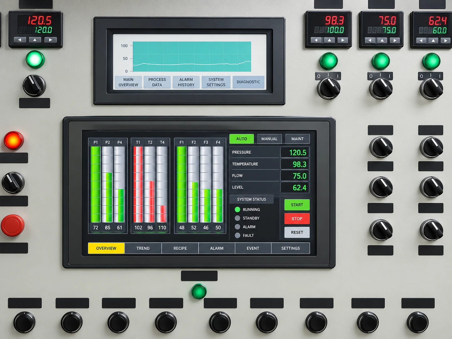
The PLC control cabinet supports HMI and push-button operation, 100 stored recipes and online recipe switching. Foam-box width and drop-plate position are electrically coordinated; an infrared height measurement system supports foam-profile monitoring. Five spare PLC contact interfaces and corresponding HMI display provisions support future expansion. Remote communication and diagnostic interfaces are included.
| Component Group | Specified Selection |
|---|---|
| HMI / PLC | Weinview selection stated in the configuration; final model schedule to be agreed |
| Variable-frequency drives | Mitsubishi |
| Contactors, circuit breakers and control buttons | Schneider / Omron |
| Pneumatic valves and cylinders | AirTAC |
| Key drive motors | Siemens |
| Bulk polyol metering pumps | Viking |
| Selected minor-component metering devices | Shimadzu / imported pumps as listed |
Brand selections describe this configuration and are confirmed against the final bill of materials. Magnetic-coupled TDI and MC drives and multiple sealing arrangements are specified to reduce leakage paths; no zero-leakage performance guarantee is inferred.
Structural and Factory Interfaces
| Structure | Material Specification |
|---|---|
| Tunnel frame | 150 × 150 mm H-section |
| Side-conveyor supports | 100 × 50 × 4 mm rectangular tube |
| Conveyor main frame | 125 × 125 mm H-section |
| Chain-support upper / lower / middle frames | 75 × 50 × 4 / 60 × 40 × 4 / 50 × 50 × 4 mm rectangular tube |
| Two-side working walkways | No. 8 channel-steel welded construction |
The factory supplies the main electrical connection, circulating cooling-water source, main compressed-air source and outdoor discharge ductwork for the tunnel exhaust fans. Coordinate these utilities with tank placement, access routes, curing space and downstream cutting equipment before finalizing the layout.
Previously Listed Reference Configuration
The following values relate to the earlier configuration on this solution page: 6–12 material streams, 15–65 kg/m³ density, equipment output range 300–450 kg/min, block width up to 2,200 mm and height up to 1,250 mm. The related customer application operates at 300 kg/min. These values are not the specification or performance record of the new 13-component line.
| Technical Parameter | Standard Specification / Value | Engineering Context & Verification |
|---|---|---|
| Target Application | Sofa Cushions, Mattresses, Soft Furniture Padding | High-resilience flexible foam blocks |
| Material Matrix | Polyether Polyol + TDI / Polymeric MDI | Wide-hardness flexible polyurethane |
| Foam Density Range | 15 – 65 kg/m³ | Adjustable across standard, HR, and memory foams |
| Chemical Streams | 6 to 12 Independent Metering Streams | Polyols, TDI, water, blowing agents, catalysts |
| Equipment Configuration Output Range | Up to 300 – 450 kg/min | 300 kg/min in the reference customer application |
| Block Dimensions | Width: Up to 2,200 mm; Height: Up to 1,250 mm | Rectangular flat-top block dimensions |
| Top Skin Waste | ≤5% Trimming Loss | Enabled by flat-top leveling technology |
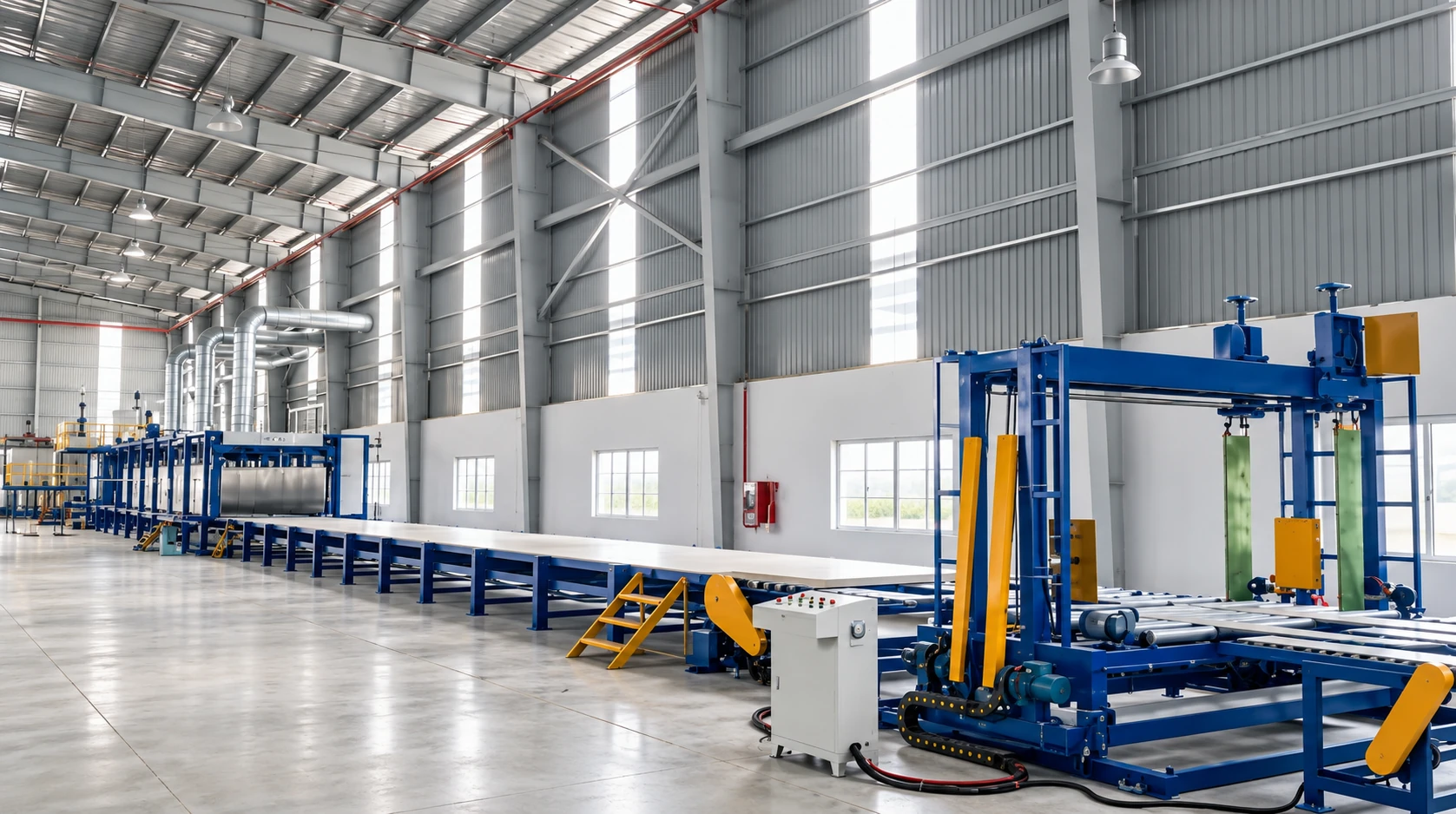
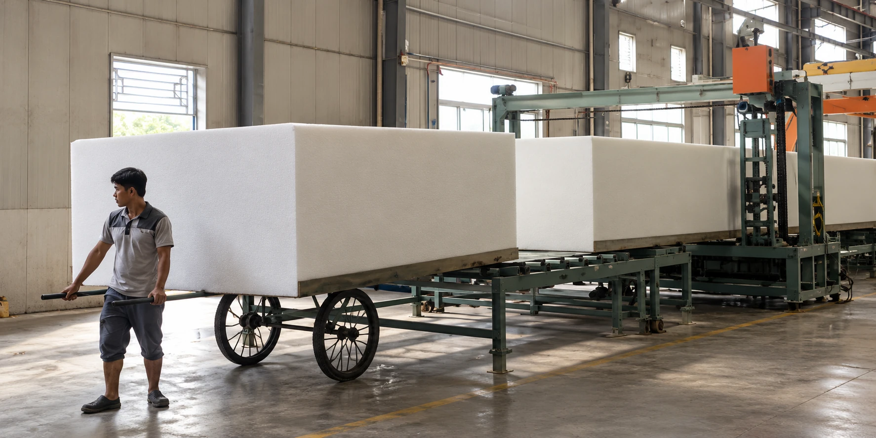
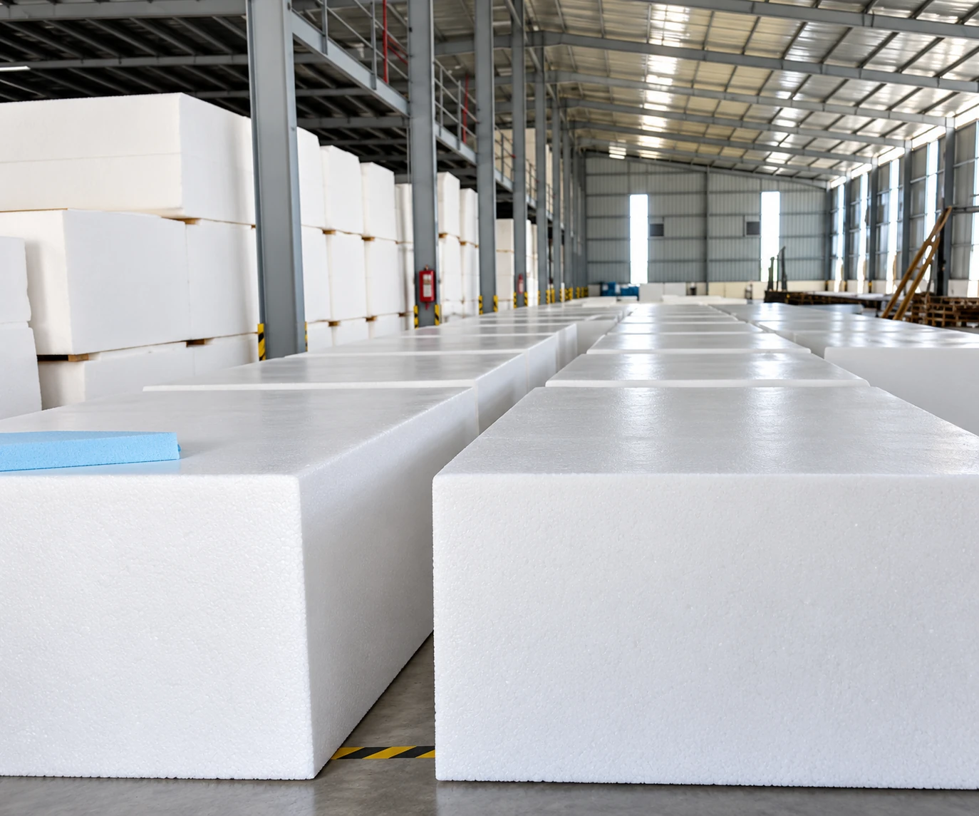
Continuous Slabstock Foaming Equipment and Process Gallery
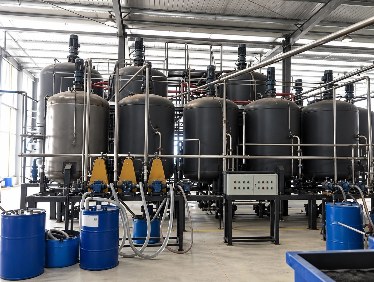
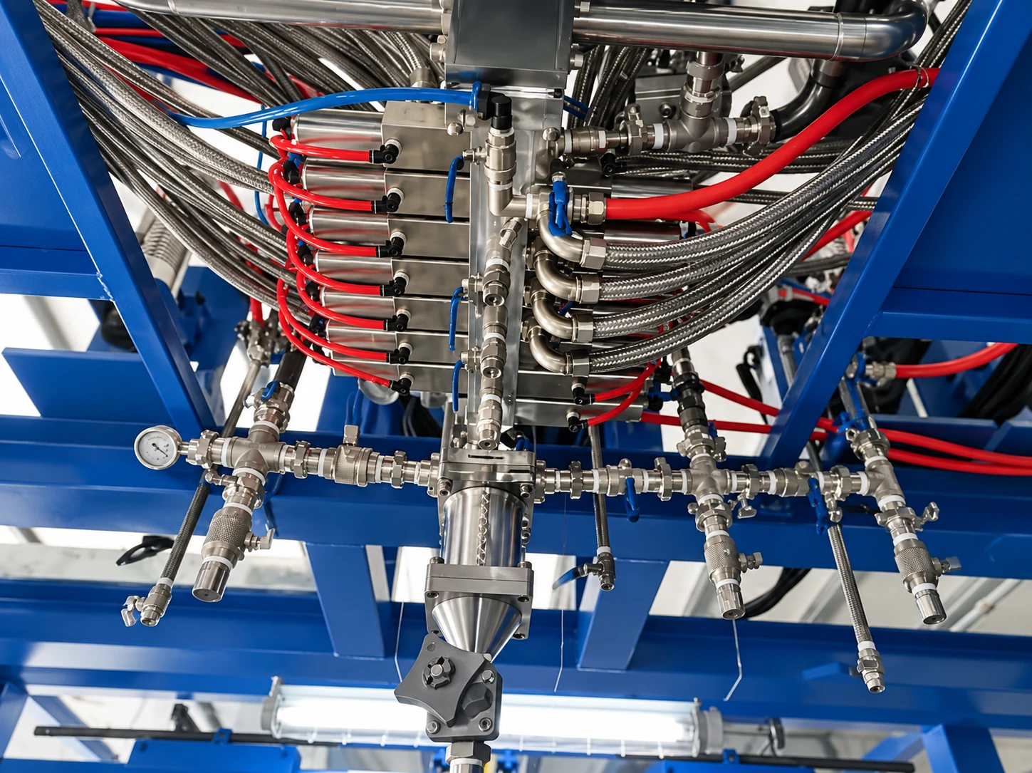
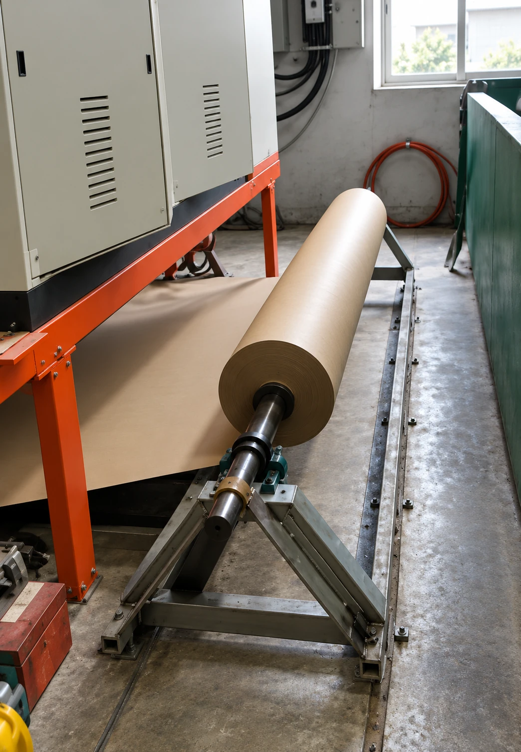
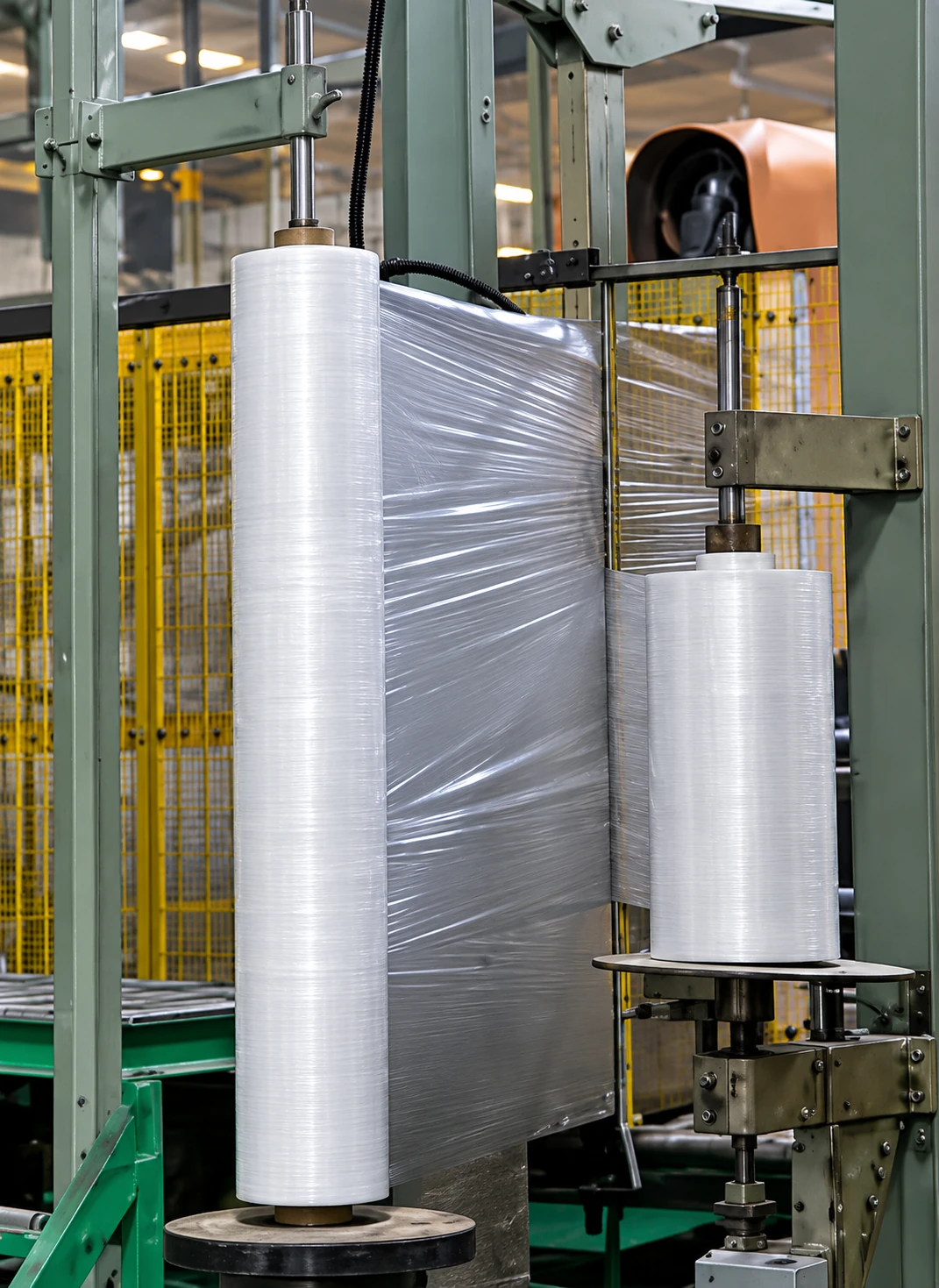
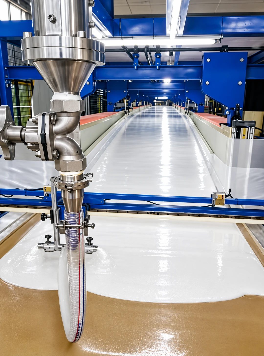
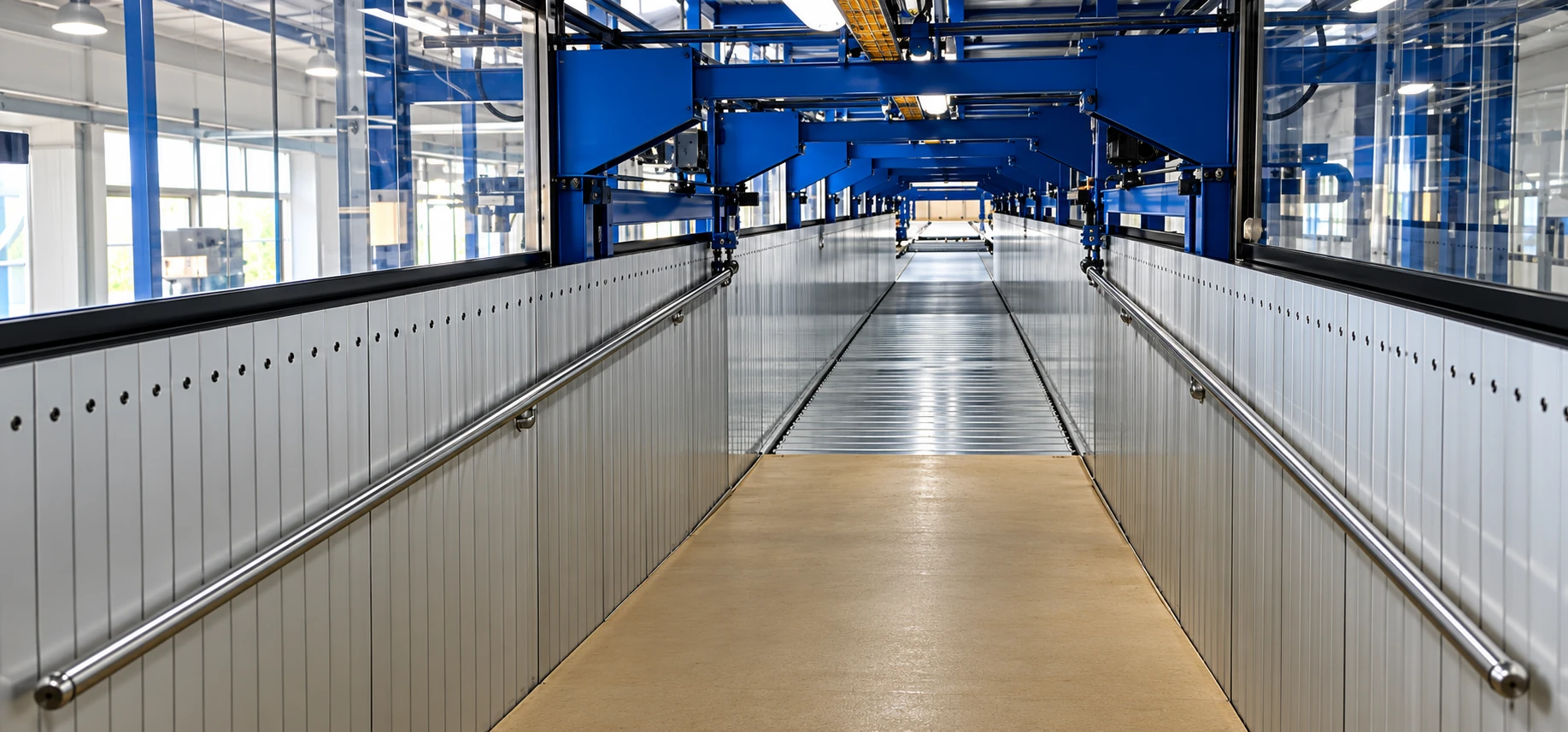
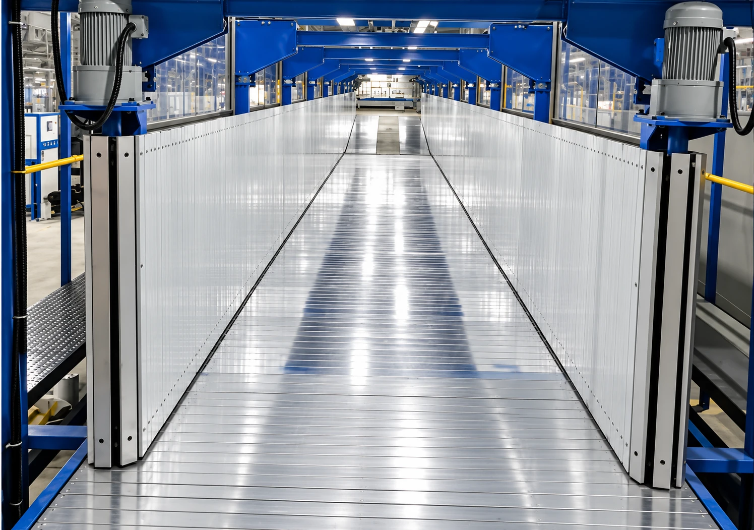
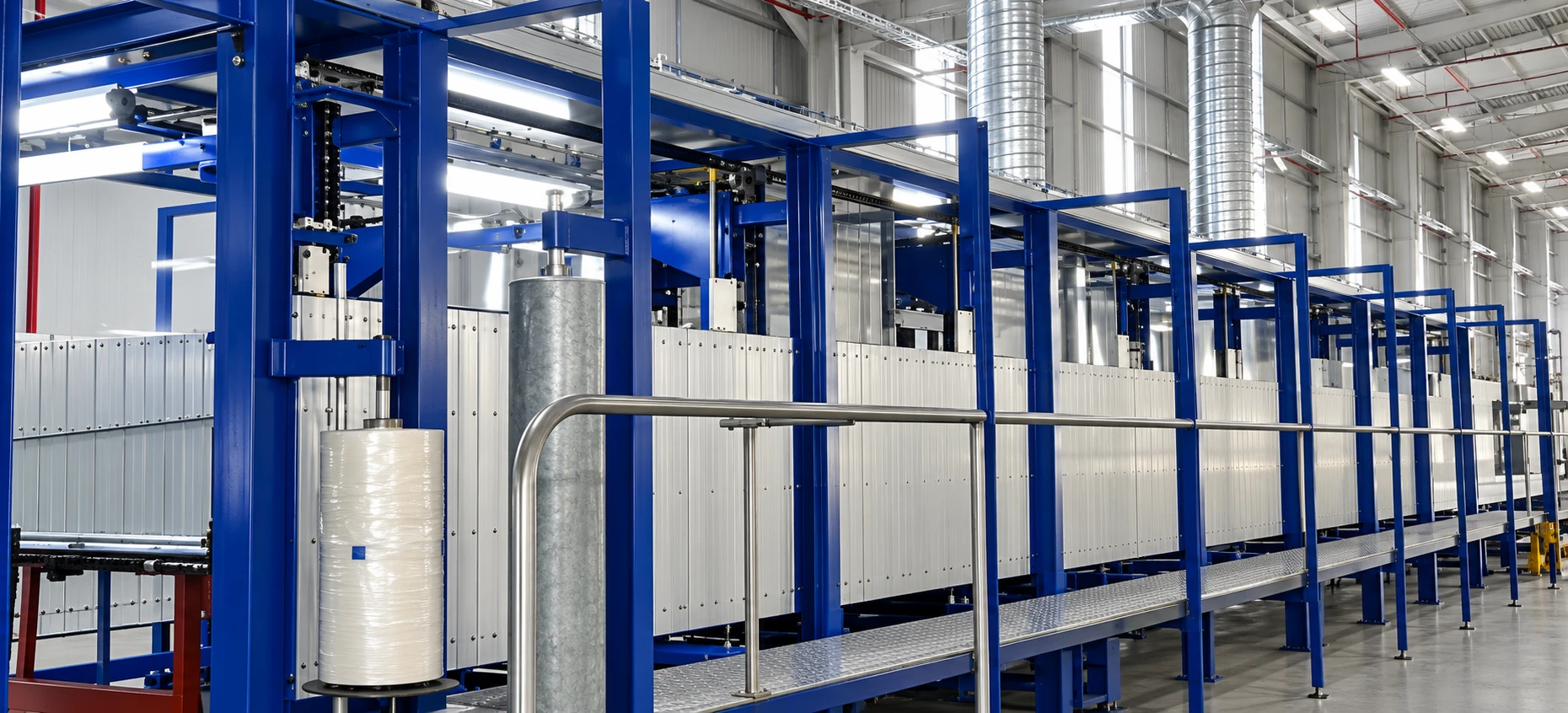
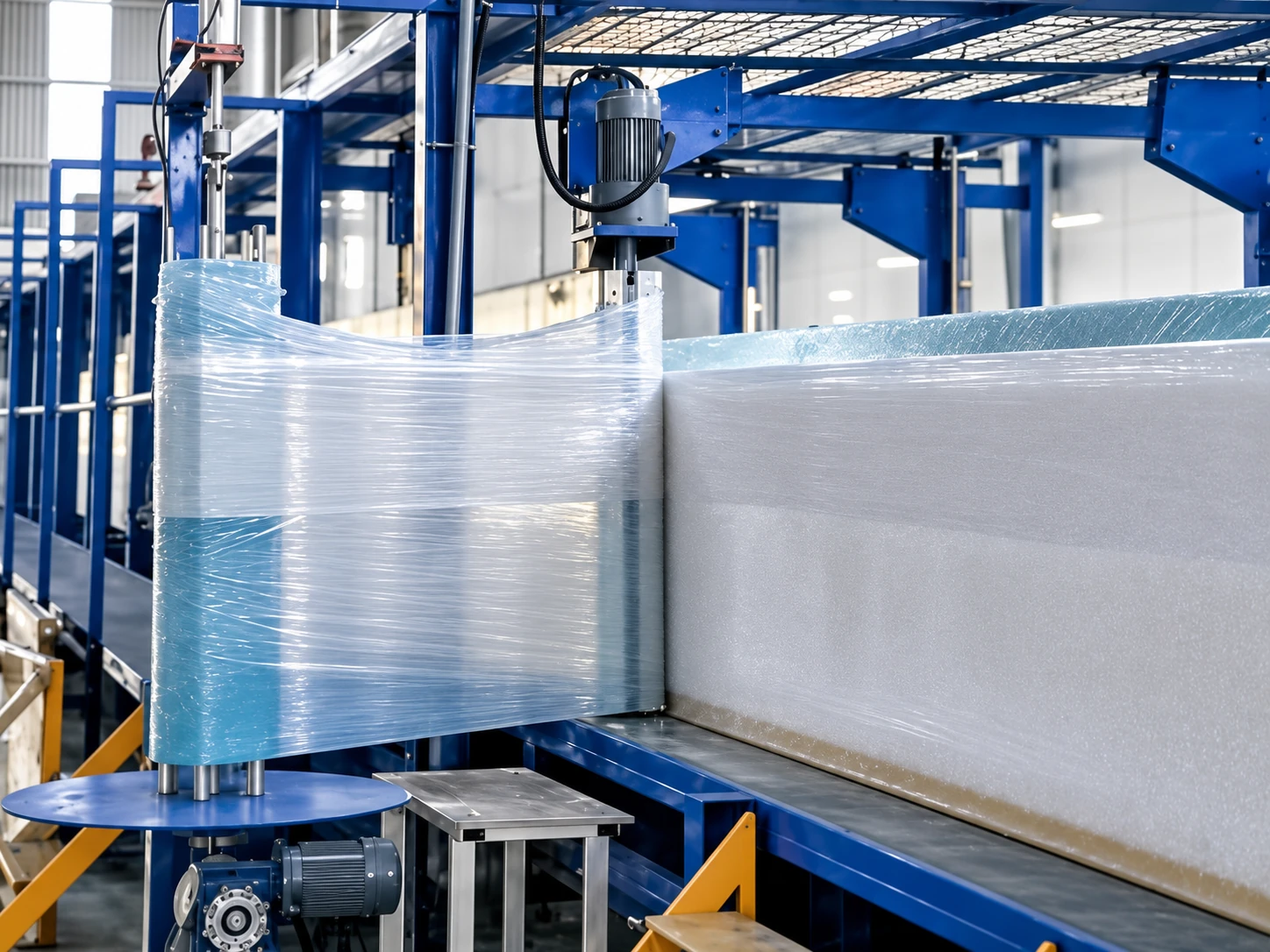
Equipment and process illustrations show material handling, metering, mixing, liner supply, continuous forming and block handling. They explain the process arrangement; final equipment layout and specifications follow the selected configuration.
Material Storage, Metering and Control
Paper and Film Supply
Pouring and Continuous Forming
Cut-Off and Block Transfer
Foam Block Storage and Conditioning
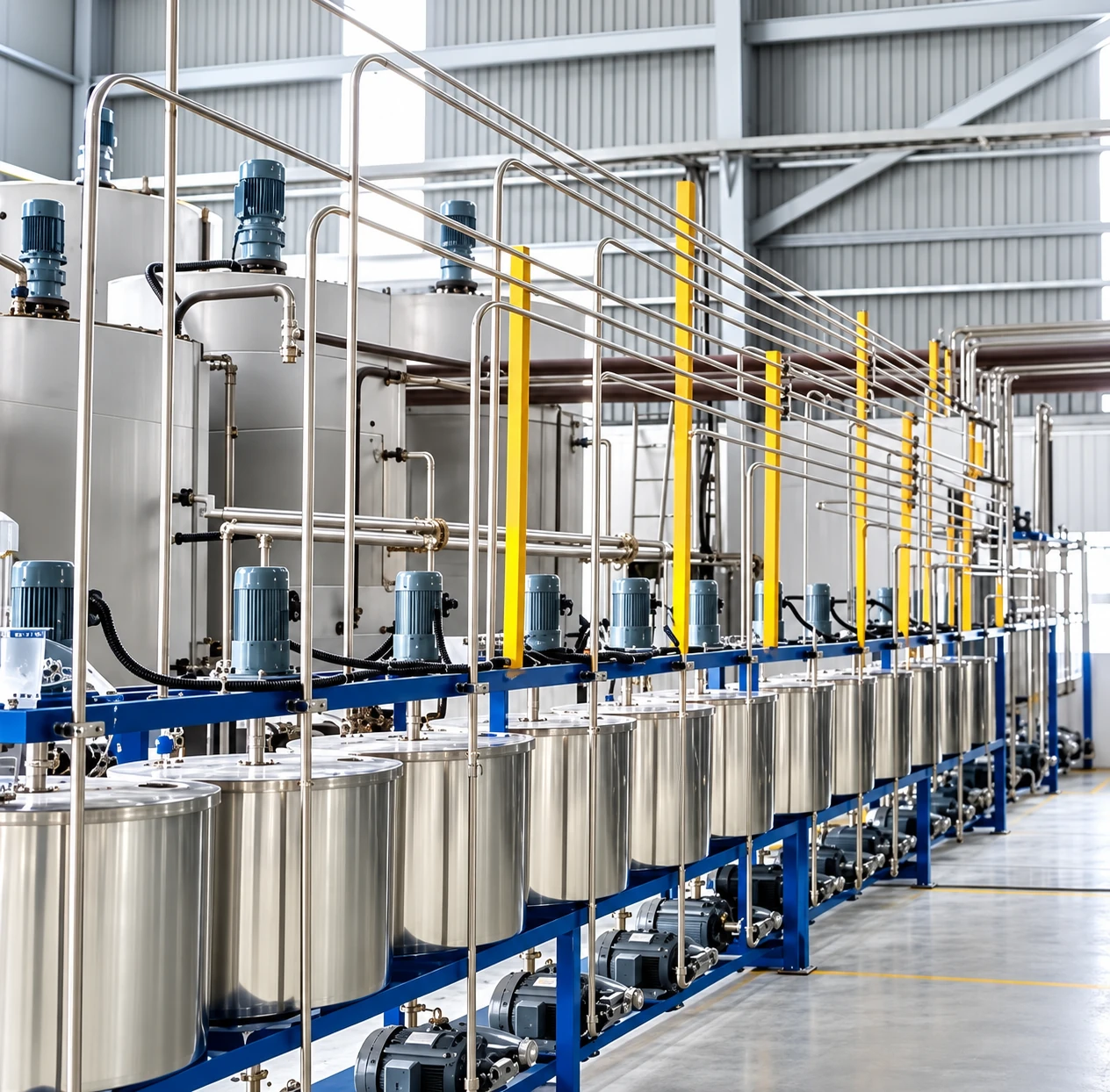
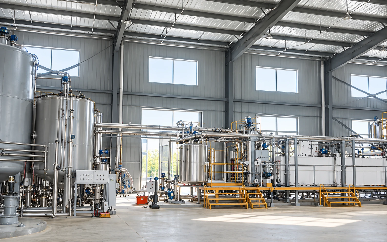
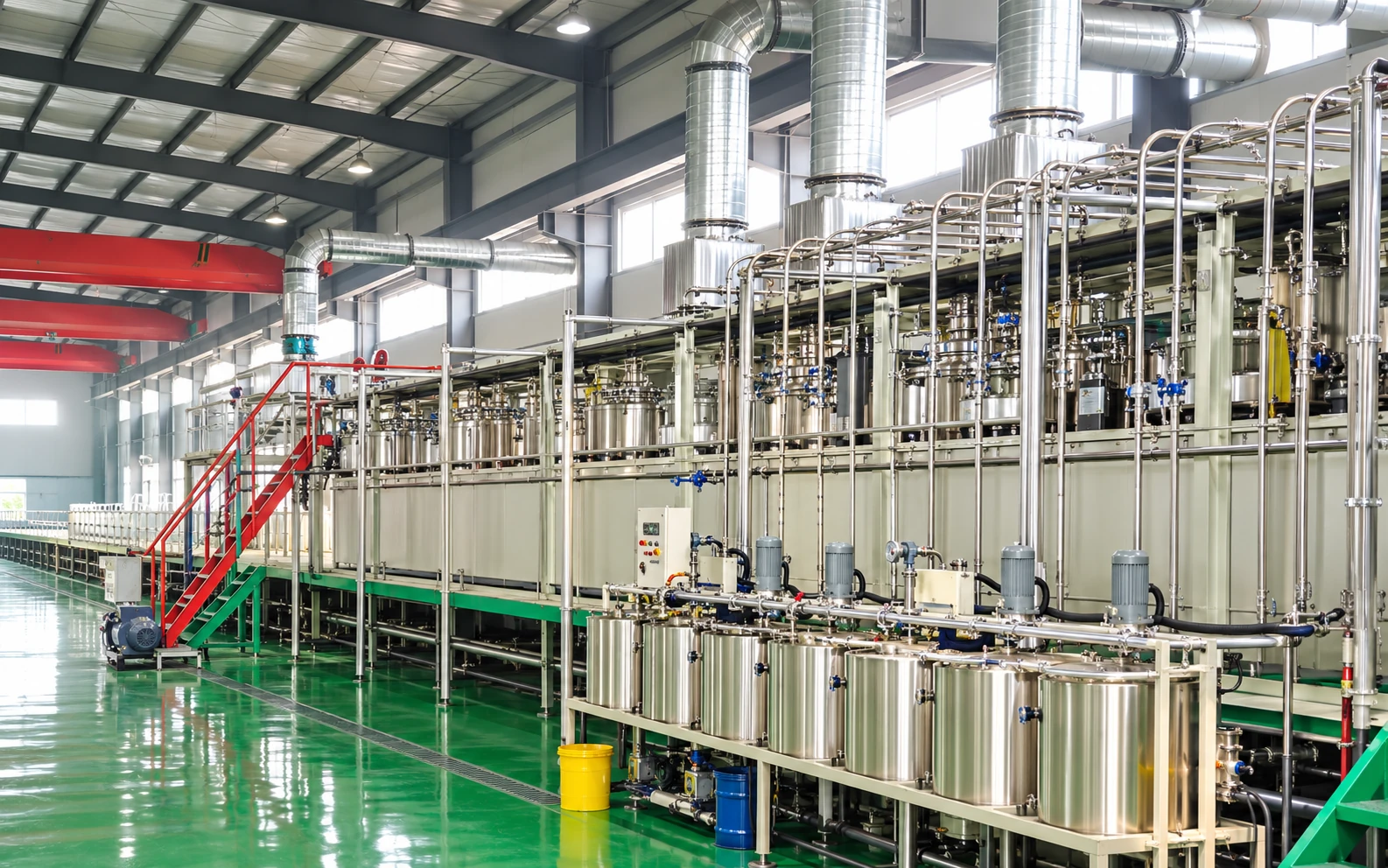
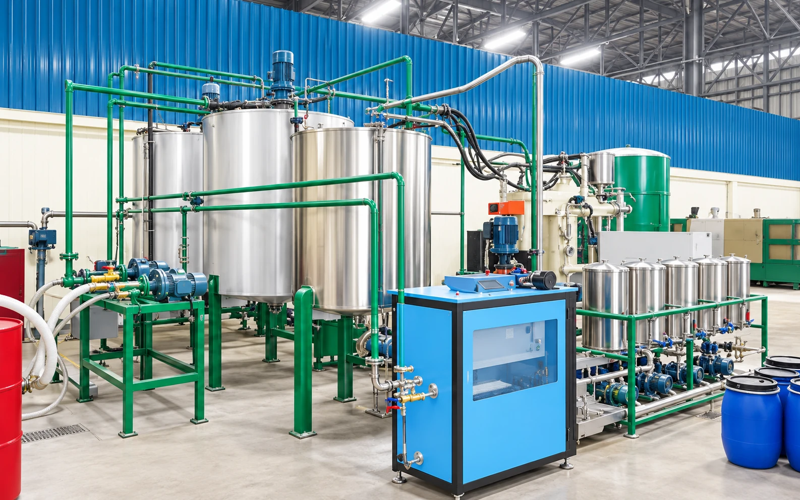
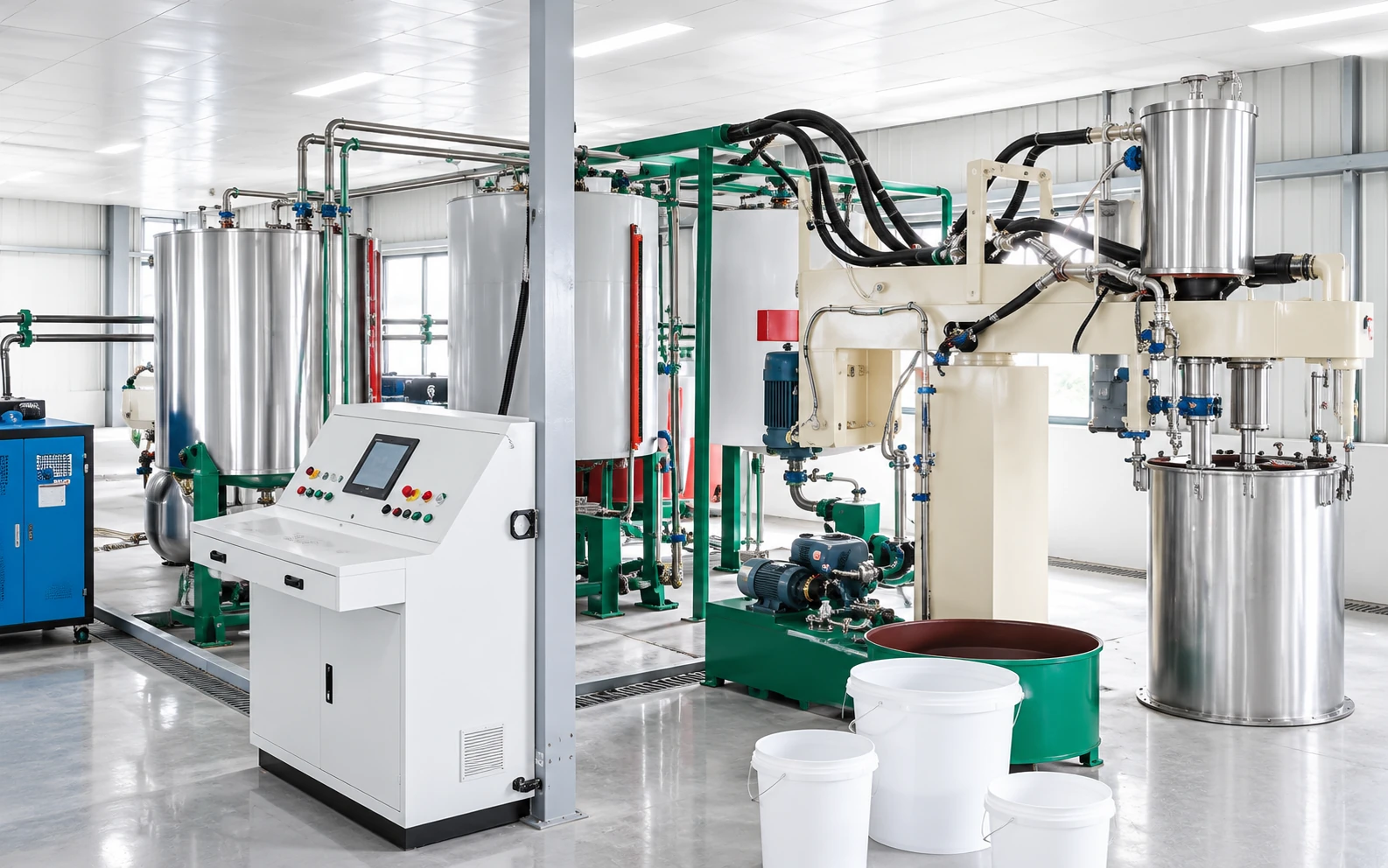
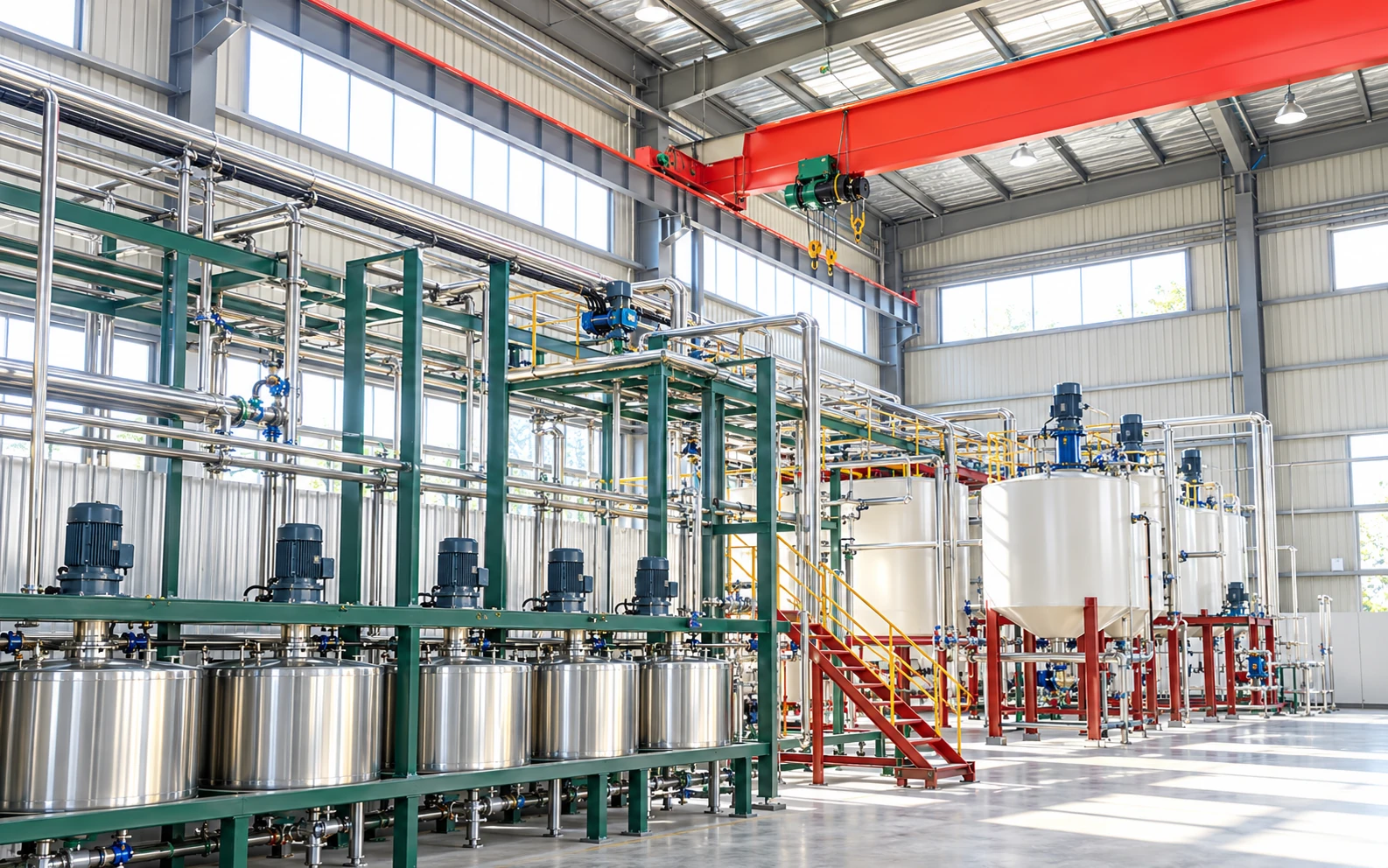
Material Storage and Feed Equipment Reference Gallery
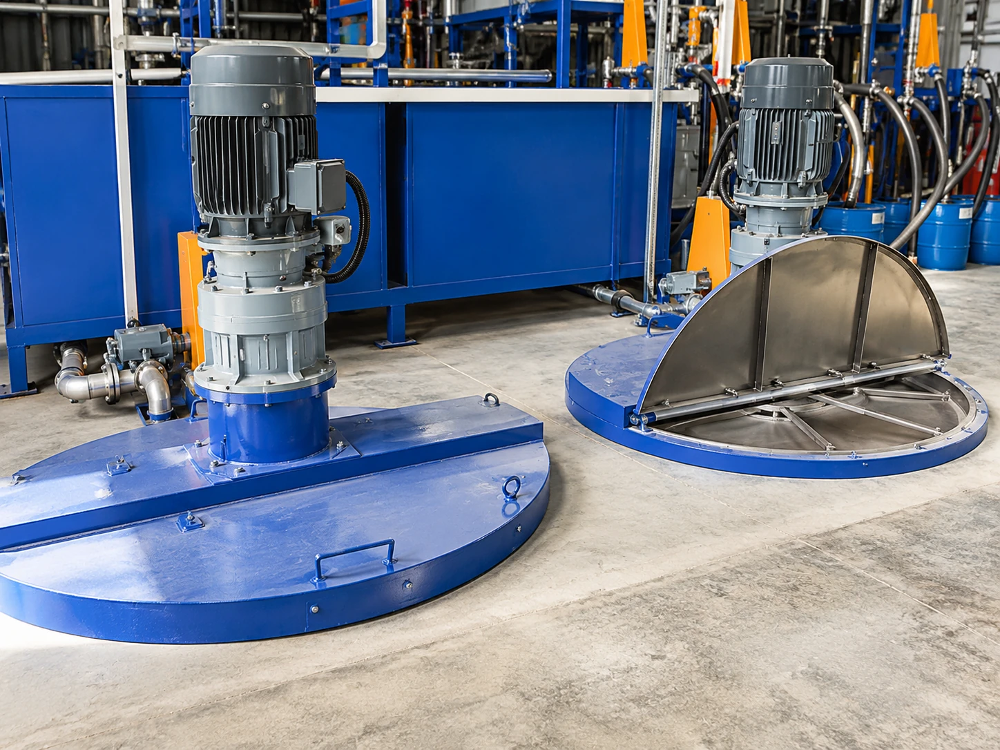
Reference illustrations show material-storage, feed-piping and metering arrangements for process planning. The standalone metering unit is an auxiliary equipment reference; the installed material circuits and line layout follow the selected configuration.
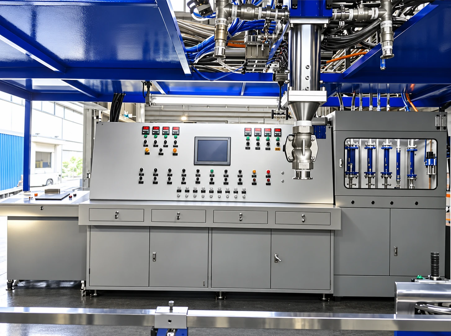
Continuous Slabstock Foaming Control and Forming Module Gallery
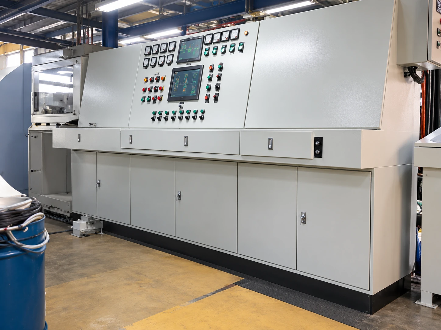
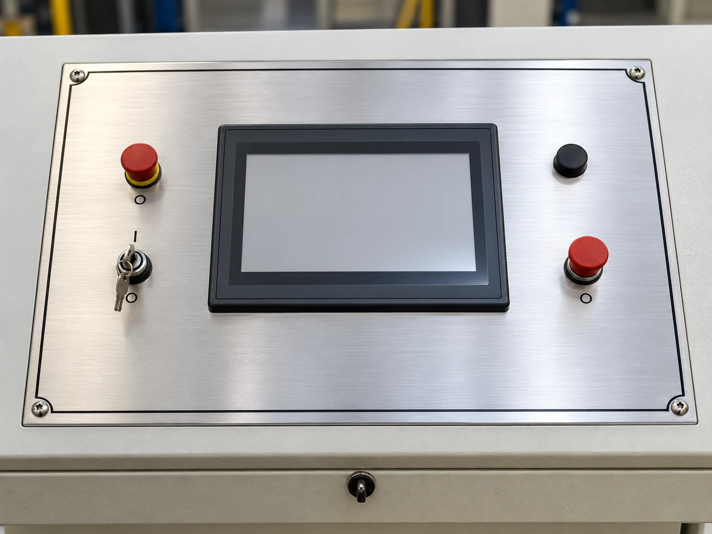
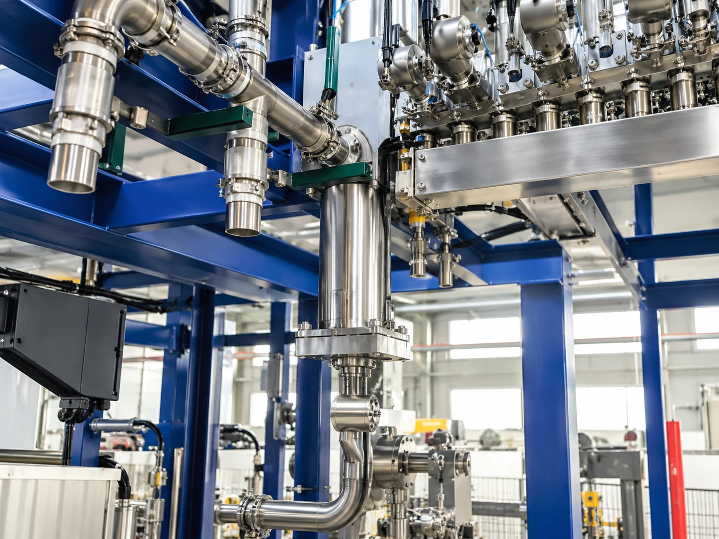
Equipment illustrations show operator and material-temperature controls, recipe interfaces, mixing and dispensing assemblies, overflow-trough arrangements, continuous forming and powder preparation. They explain equipment functions; numerical ratings, material circuits and control functions follow the selected engineering configuration.
Operator, Temperature and Recipe Controls
Mixing and Dispensing Modules
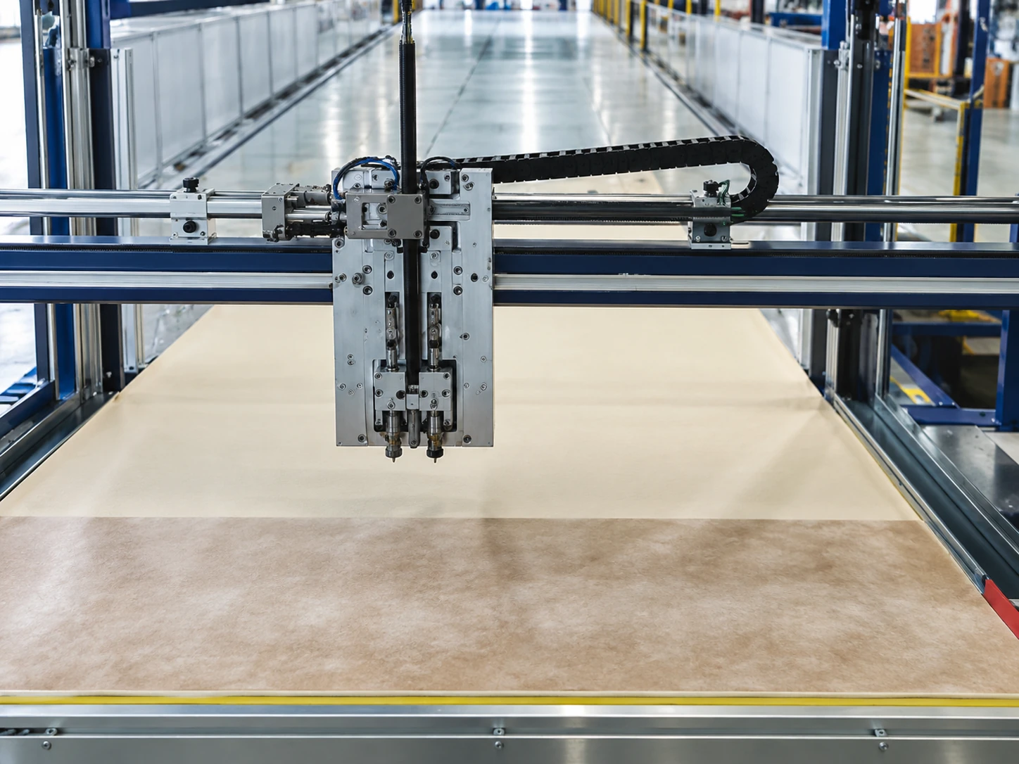
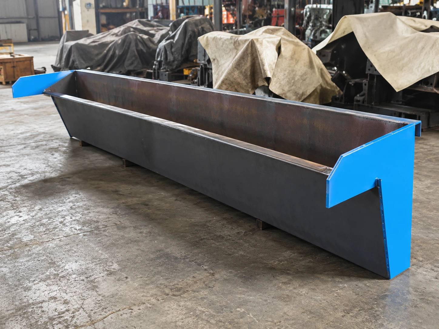
Drop Plates and Continuous Forming
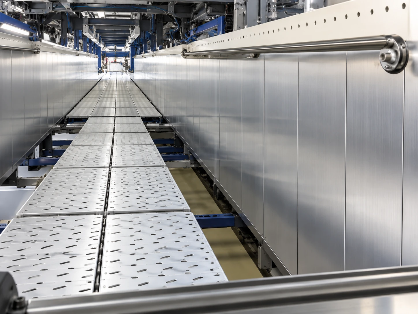
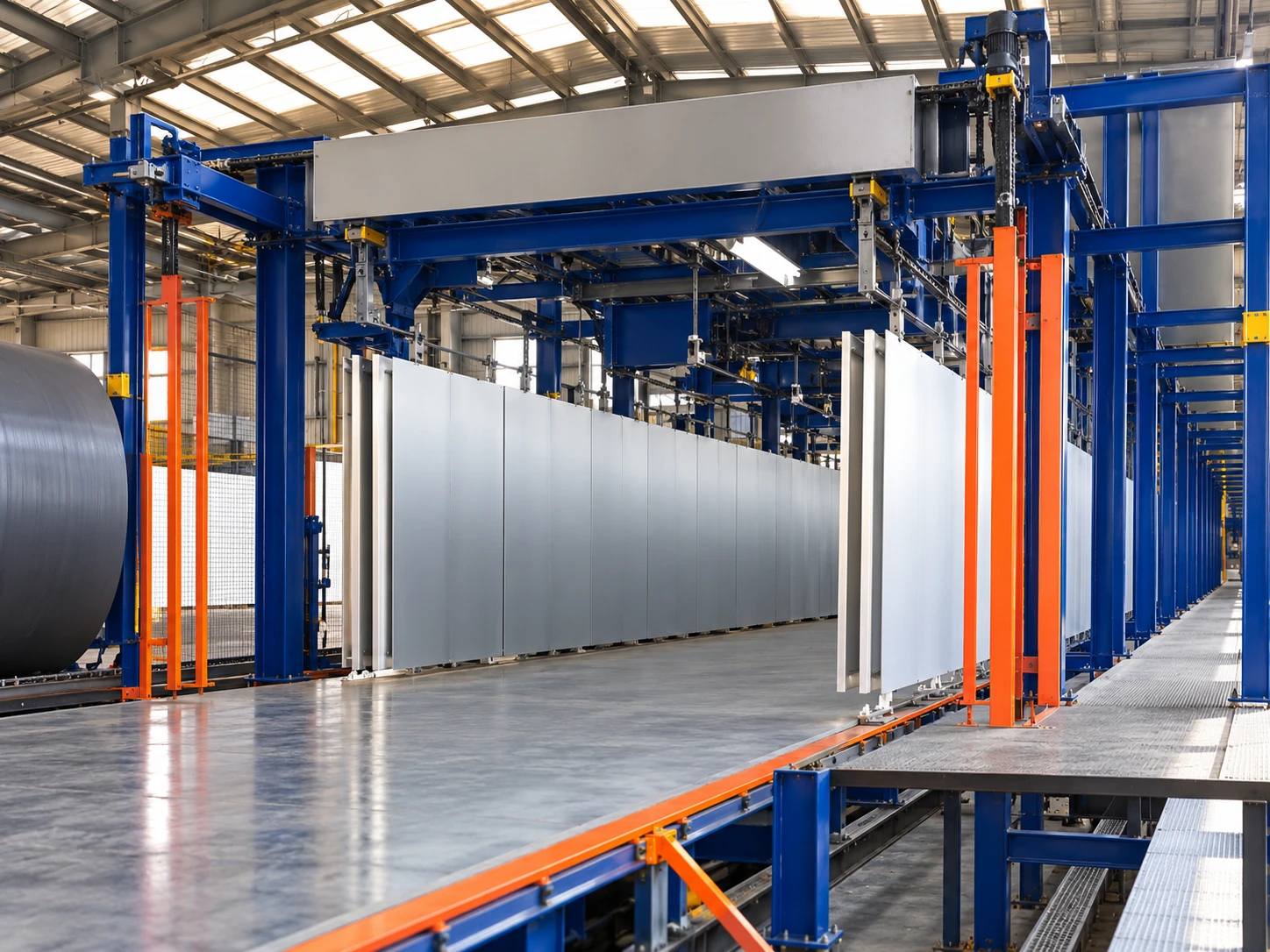
Powder Preparation Equipment
Equipment for This Solution
Review continuous foaming, cutting and auxiliary equipment for the selected line. Box Foaming equipment shown among related products represents a separate batch-process option.
Continuous Slabstock Foaming Line | Foam Blocks
Continuous Slabstock Foaming line with multi-stream metering, low-pressure dynamic mixing, conveyor forming and cut-off for flexible PU foam blocks.
PU Foam Cutting and Slicing Equipment | Foam Blocks
Haifeng supplies PU foam cutting equipment for slabstock blocks, with synchronized cut-off and configurable slicing or CNC contour modules for furniture padding.
Low-Pressure Box Foaming Machine | Foam Blocks
Low-pressure polyurethane metering and dynamic mechanical mixing for batch Box Foaming. The reactive mixture is poured into a box mold for free rise, then the foam block is cured and conditioned before slicing. Configure the machine to the formulation, block dimensions and required production capacity.
Low-Pressure PU Foaming Machine | Mattress Soft Sponge
Low-pressure PU foaming machine designed for mattress soft sponge production, ensuring uniform fine cells and high resilience. Widely used in furniture and bedding manufacturing applications.
Precision Vacuum Horizontal Foam Cutter | Thin Foam Sheets
Slices foam blocks using digital settings, automatic reciprocating travel on rails and a vacuum worktable. Pressure rollers help retain the foam during cutting.
Rail Mounted Horizontal Foam Slicer | Long Foam Buns
Slices long foam buns into sheets using digital thickness settings and automatic reciprocating rail travel. It can form part of the downstream cutting arrangement of a slabstock plant.
Automatic Vertical Foam Cutter | Foam Block Conversion
Cuts foam vertically with touchscreen and PLC settings for multiple thicknesses. A fixed aluminum worktable holds foam between retaining plates while the blade carriage travels on linear guides.
Horizontal Blade CNC Foam Contour Cutter | Shaped Foam Components
Follows programmed contours using computer control, multi-axis motion control and servo drives. A circulating band blade cuts shaped foam components; an automatic pressure-roller arrangement is optional.
Foam Roll Compression Packaging Machine | Flexible Foam Roll Packaging
Compresses foam rolls while wrapping them in packaging film, followed by sealing and cutting. The described arrangement includes automatic loading and unloading.
Foam Cell Opening Compression Machine | Flexible Foam Conditioning
Compresses flexible foam through rollers for cell-opening conditioning. The required compression setting and material response are reviewed for the foam formulation.
Key Engineering Advantages
Configuration features for recipe handling, material circuits, adjustable forming and process observation.
Recipe and Expansion Interfaces
100 stored process recipes, online switching and five spare PLC interfaces support formulation management and future engineering expansion.
Coordinated Electric Adjustment
Foam-box width and drop-plate position are electrically coordinated; side conveyors and the flat-top device support the selected bun geometry.
Process Observation and Height Measurement
Tunnel observation windows and infrared foam-height measurement support operator monitoring of rise and forming.
Remote Diagnostics and Utility Integration
Remote communication interfaces support diagnostics; the factory utility plan coordinates power, cooling water, compressed air and exhaust ducting.
Related Project Case
Review the production configuration, delivery and results.
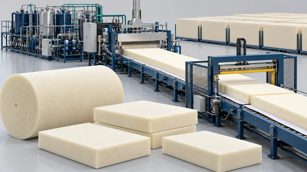
Continuous Slabstock Foaming Project in Brazil
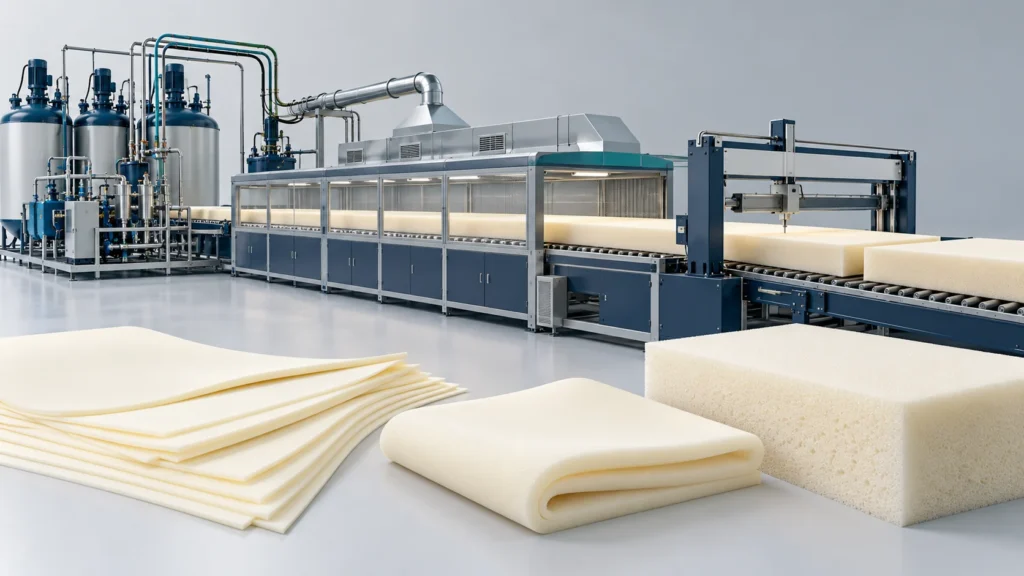
Furniture Padding Flexible PU Line Project in Argentina
Frequently Asked Questions
Answers on process selection, equipment integration and delivery support.
What is included in the 13-component configuration?
Do the five reserved interfaces mean 18 installed metering streams?
Does 350 kg/min replace the earlier 300–450 kg/min specification?
What foam widths, heights and densities are specified?
Can recipes and pouring modes be changed?
How does the line form and cut the foam bun?
What utilities must the factory provide?
How does Continuous Slabstock Foaming differ from Box Foaming?
Are existing customer-case results guaranteed for this configuration?
Discuss Your Furniture Production Project
For a 13-component Continuous Slabstock Foaming line, share the formulation and stream requirements, target density, foam dimensions, output, utility conditions, curing space and downstream cutting plan so Haifeng can confirm the configuration and interfaces.


