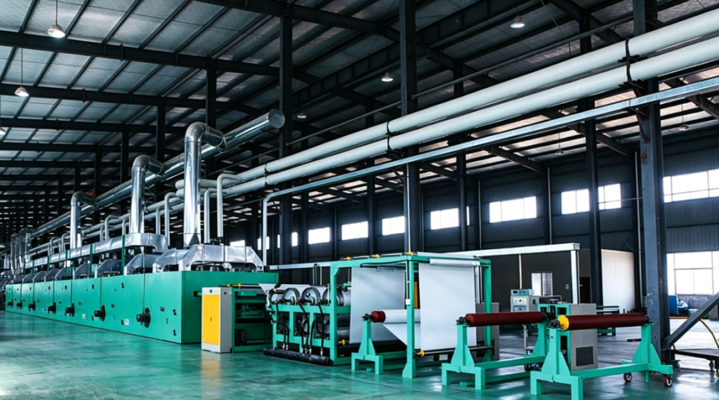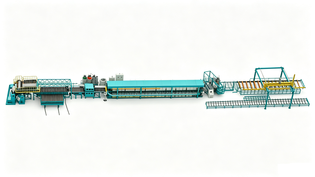

Automating HP-RTM preforming pays off when ply placement, not resin injection, sets the pace of the line, and when ply position is what drives your reject rate. Below that point, a manual layup cell working with an accurate cutting table and a temperature-controlled preform press usually builds the same laminate for less capital. The decision rests on four numbers: annual part volume, plies per preform, the number of distinct stacks you run, and the fabric scrap you already accept. This guide sets out the thresholds worth checking before a cell is signed for, and the conditions under which manual preforming remains the better choice.
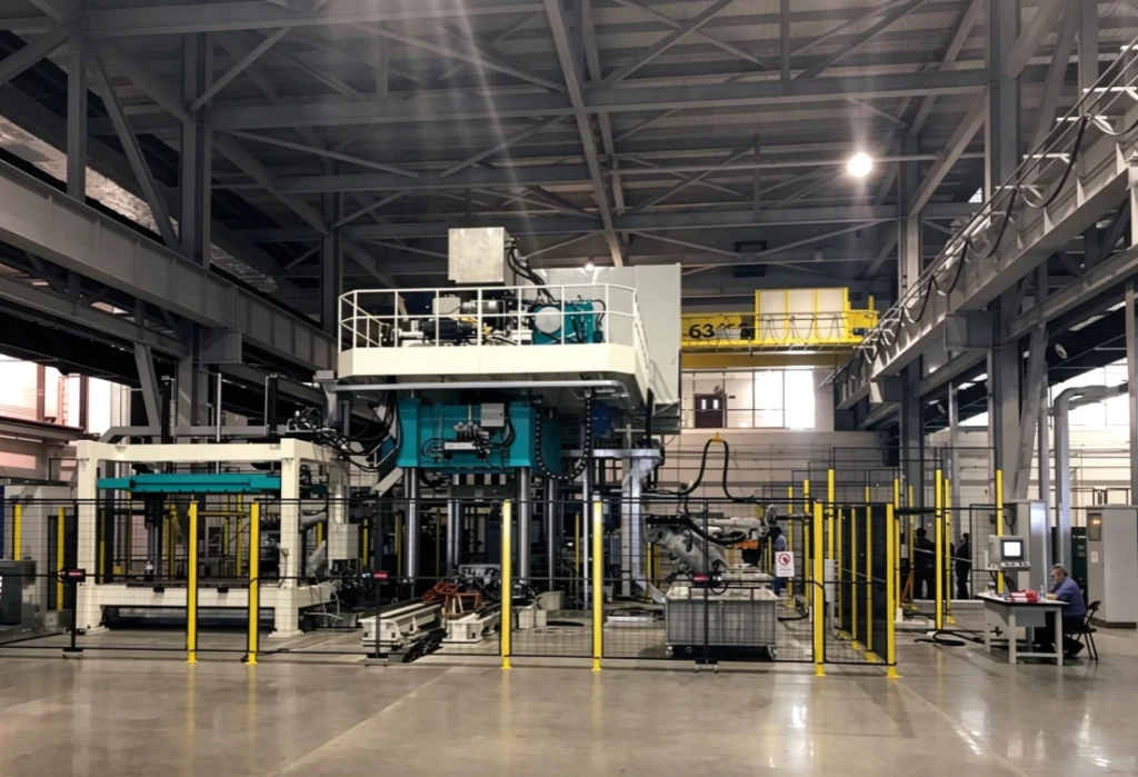
What Changes When Preforming Moves From Manual to Automated
Manual preforming is a sequence of tolerances that never appear on the part drawing. An operator receives kitted plies, places them in the preform tool in a fixed order, applies binder, and closes the tool for consolidation under heat and pressure. Ply position shifts with the operator, the shift, and how the previous ply draped. Binder distribution shifts with how evenly the scatter was applied. Preform stiffness shifts with how long the tool sat at temperature.
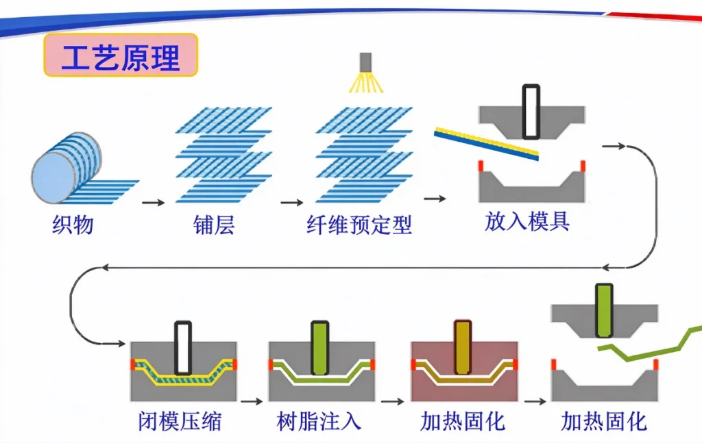
Automation replaces that judgment with a program: nested cutting, single-ply pick with vision alignment, controlled binder activation, and a forming step held at a set pressure and temperature. The gain is not that a machine moves faster than a skilled laminator. The gain is that ply position and binder activation repeat, part after part, and become numbers you can inspect.
That repeatability matters more in HP-RTM than in open molding, because the injection stage has very little tolerance for preform variation. Resin enters under high pressure and gels quickly, so the flow path through the cavity is set by the preform’s permeability. A gap between plies opens a low-resistance channel; the flow front runs along it and reaches the vent before the surrounding laminate is wet, leaving a dry region elsewhere. An overlap does the opposite, thickening the preform locally, raising fiber volume fraction, and producing a pressure spike where the mold closes on it.
Neither failure is corrected downstream by tightening the metering unit. Ratio control keeps the resin chemistry where it belongs; it does not restore fiber architecture. A preforming decision is therefore a decision about how much permeability variation and thickness variation the part can carry before the laminate stops behaving the way the simulation assumed.
A preform only becomes a structural part once it is closed in a mold and injected under pressure. <SRIM Explained Structural Reaction Injection Molding Basics> covers how structural reaction injection molding pairs a fiber preform with a reactive resin system.
Which Production Signals Justify an Automated Preforming Cell
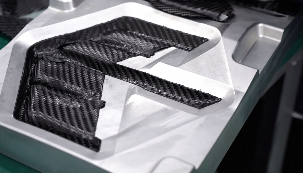
Volume alone is a poor test. A plant running large, simple, two-ply panels at high rate may never need a robot, while a plant running fewer but deeper twenty-ply structural stacks may need one at a fraction of that volume. The signals that matter are cycle position, placement count, and where the errors actually come from.
| Signal | Manual still holds | Automation earns its place | What drives the difference |
|---|---|---|---|
| Cycle position | Preform making fits inside the injection cycle with time to spare | Preform making sets the rhythm of the line and the press waits | The cell must remove a constraint, not add capacity nobody uses |
| Plies per preform | Few plies, simple stack, short layup sequence | High placement count where each ply is another chance to drift | Position error accumulates through the stack |
| Variant mix | Long runs of one or two stacks | Many stacks with frequent changeover and program recall | Changeover becomes a data task rather than a retraining task |
| Position tolerance | Preform thickness and ply position stay off the control plan | Part stiffness depends on fiber orientation defined by drape simulation | Permeability and local fiber volume fraction follow ply position |
| Fabric scrap | Offcuts are reused, or fabric cost is small next to labor | Fabric utilization is a visible cost line on the part | Nesting and placement accuracy both cut waste |
| Labor | Skilled laminators are available and stable | Placement skill is the constraint on output | Automation moves the constraint to tooling and programming |
Start with cycle position. Measure the preform cycle at the production ply count, on production fabric, with the tool at production temperature. A trial that runs a reduced stack reports a cycle the line will never see, and it hides the part of the cycle where handling, not forming, takes the time.
Placement count is the second signal. Each ply is one more opportunity for a drift the next ply does not correct. Manual placement against a laser projection can be accurate to a few millimetres, which is fine for a cosmetic panel and not fine for a part whose stiffness was calculated around a defined orientation. The question is not whether manual placement is accurate, but whether the required accuracy is written into the part’s control plan.
Variant mix is the signal most often missed. Where a manual cell asks operators to remember twelve sequences, an automated cell asks for twelve programs. If changeover is already costing you a shift per switch, the economics of a cell change quickly, and they change for reasons that have nothing to do with labor cost per hour.
Scrap has to be counted by cause before it can be used as an argument either way. Cutting waste, placement rework, and rejected preforms are three different problems, and only the first two are addressed by automating the cell.
Where Manual Preforming Is Still the Right Answer
Automation is capital that has to be recovered from a specific stack, and there are configurations where it cannot be.
- Low annual volume. Programming, tooling and gripper development are fixed costs per stack. A stack that runs a few weeks a year rarely carries them.
- Large parts with few plies. Reach, press size and tooling cost scale with footprint while placement count stays low, so the cell is expensive and the labor it replaces is small.
- Double-curvature first plies. Fabric that will not drape without wrinkles is often placed by hand for the first one or two plies, with the rest automated. That hybrid is a deliberate configuration, not a compromise.
- Development work. When the stack changes faster than a program can be validated, manual layup reaches a sample sooner.
- Constraints that sit elsewhere. If trimming, bonding or the injection cell limits output, automating preforming adds capital without adding saleable parts.
One intermediate step deserves separate consideration. If the real problem is ply accuracy and nesting rather than placement speed, automating the cutting table alone often fixes more than expected: plies arrive numbered, outlines match the simulation, and manual placement becomes both faster and more consistent. That is a much smaller commitment than a full cell, and it tells you whether placement is genuinely the remaining constraint.
It is also worth confirming that the part needs a continuous-fiber preform at all. Some structural parts are molded with reinforcement carried in the resin rather than in a draped stack, and the equipment route changes completely when they are.
Not every structural part needs a continuous-fiber preform. <RRIM Vs RIM Which Process Suits Your Structural Part> covers how reinforced and unreinforced reaction injection molding differ when a part has to carry load.
What an Automated Preforming Cell Actually Contains
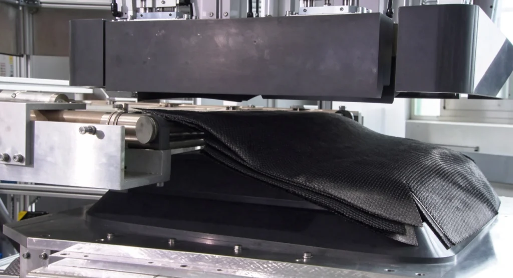
A preforming cell is not one machine. It is a chain of stations, and the decision at each station is separable, which is useful when the budget has to be staged.
| Cell element | What it decides | Where it fails if underspecified |
|---|---|---|
| Nested cutting | Ply outline accuracy and kitting sequence | Ply numbering breaks and a wrong ply enters the stack |
| Single-ply pick with vision alignment | Placement repeatability on limp fabric | Fabric distorts on pick and position drifts at the edge |
| Binder application and activation | Green strength and preform thickness | The preform deforms during transfer and wrinkles in the mold |
| Forming tool and press | Three-dimensional shape fidelity and thickness distribution | Corner thinning and bridging over tight radii |
| Transfer into the RTM mold | Preform position inside the cavity | Edge mismatch and resin bypass at the perimeter |
| Ply verification record | Traceability per preform | A customer audit cannot be closed from production data |
Cost is driven by placement events, not by floor area. Ply count multiplied by placement time sets the number of grippers and stations you need; tooling sets per stack multiply with the variant mix; and gripper design has to suit the fabric, since areal weight, binder tack and fiber type all change how reliably a single ply can be lifted without distortion.
The cell also has to be planned together with the injection side rather than before it. Preform carrier design, mold loading sequence, and the metering unit’s cycle interact directly: a preform that arrives at the mold two minutes late costs more than a preform that was placed two minutes slower. Where the preform is consolidated in a separate press, the cooling and handling time between demolding and loading belongs in the same calculation as the injection cycle.
How to Run a Preform Trial That Settles the Question
A preform trial costs a fraction of a cell and it can settle the question, but only if it separates two different claims: that the cell can make this preform, and that the preform makes a good laminate.
Run the Trial on Production Fabric and Production Tooling
Same fabric lot, same binder type and content, production tool temperature, production ply count, and enough consecutive preforms to show drift rather than a good first hour. Record cycle time per preform, ply position against the projection, preform thickness at defined points, wrinkle score, and scrap mass. A trial run on a shortened stack or a substitute fabric measures the machine and not the process.
Separate Preform Acceptance From Laminate Qualification
Preform metrics accept the preform. They do not qualify the part. The laminate is qualified by mechanical testing of coupons cut from a molded panel, and by a mold filling trial at production injection pressure and resin temperature. In-plane tensile and flexural properties are commonly measured to ASTM D3039 and ASTM D7264 [1], [2]. If a trial reports only a cycle time and a photograph, it has answered the easier half of the question.
| Trial observation | What it supports | Do not infer |
|---|---|---|
| Cycle time over a full shift at production ply count | Capacity of this cell for this stack | Throughput for a different ply count, fabric or binder |
| Ply position measured against the projection | Placement repeatability of this gripper on this fabric | Laminate structural allowables |
| Preform thickness and wrinkle score | Shape fidelity in this tool | Mold filling behaviour at production injection pressure |
| Scrap mass per preform | Fabric utilization for this nesting | Cost per part without your own fabric price |
The distinction matters commercially as much as technically. A supplier who reports a cycle time has shown that the cell runs. A supplier who reports a process window, with the drift at which thickness or position leaves tolerance, has shown how the cell behaves on a normal production day. Ask for the second, and ask which fabric lot and binder batch the window was measured on.
Data to Collect Before You Request a Quotation
- Part envelope and CAD, including draw direction, radii and any class A surface
- Ply schedule: ply count, orientation, fabric areal weight, binder type and content
- Annual volume, variant mix and typical batch size per stack
- Required takt time and shift pattern the cell has to hold
- Current preform cycle time, scrap rate by cause, and rework hours
- Existing cutting equipment and its nesting capability
- Press, tooling and floor space constraints, plus available utilities
- Downstream injection cycle, mold loading method, and traceability requirement
Three items change the answer more than the rest: ply count, variant mix, and the current cause of scrap. A quotation built without a ply schedule is a price for a machine, not for a cell that produces your part, and the difference usually surfaces during acceptance testing rather than during negotiation.
Send the Ply Schedule Before the Cell Layout
Tell us the part envelope, ply count and orientation, fabric areal weight and binder, annual volume with variant mix, required takt, current preform cycle and scrap by cause, and the resin system and injection cycle the preform feeds. We will review how the preforming decision interacts with the metering and injection side of the cell, and we will say plainly where that scope ends. Haifeng Polyurethane Machinery, Info@chinahaifeng.com, WhatsApp 86 13566296633.
FAQ
How many preforms per shift justify an automated cell?
There is no universal number, because two preforms of a twenty-ply stack can carry more placement work than fifty simple panels. Build the comparison from placement minutes per preform: multiply by annual volume, convert to labor hours, and compare that with the capital recovery of the cell at your own volume and shift pattern. If the result is close, automate the cutting table first and re-measure before committing to placement.
Can an automated cell handle deep or double-curved preforms?
It depends on the drape. A stack that can be formed without wrinkles in a manual tool can usually be formed automatically, provided the ply outlines come from a drape simulation and the tool has appropriate radii. Where the first plies bridge over a tight radius, a hybrid cell that keeps those plies manual and automates the rest is common and often the cheapest configuration that still holds takt.
Does automation remove the need for a preform press?
No. Binder activation and consolidation still need temperature, pressure and time. Automation changes how plies arrive at the tool and how the consolidated preform is handled; it does not change the physics of bonding the stack. A cell with poor temperature uniformity at the tool will produce variable green strength whether a robot or an operator placed the plies.
Why does a preform fault show up as a molding defect instead of a preform defect?
Because permeability and thickness are invisible until resin moves through them. A preform that looks correct can still contain a gap that channels the flow front, or an overlap that raises local fiber volume fraction. The fault appears as a dry patch or a thickness deviation after demolding, which is why preform verification is worth recording per part rather than checked by eye at the tool.
References
[1] ASTM D3039/D3039M, “Standard Test Method for Tensile Properties of Polymer Matrix Composite Materials,” ASTM International, West Conshohocken, PA.
[2] ASTM D7264/D7264M, “Standard Test Method for Flexural Properties of Polymer Matrix Composite Materials,” ASTM International, West Conshohocken, PA.
If you’re interested, check out these related articles:
RRIM Vs RIM Which Process Suits Your Structural Part
Causes Of Shrinkage In Polyurethane Foam How To Control It
What Is Spray Polyurethane Foam Composition And Application
What Is Semi Rigid Polyurethane Foam
SRIM Explained Structural Reaction Injection Molding Basics