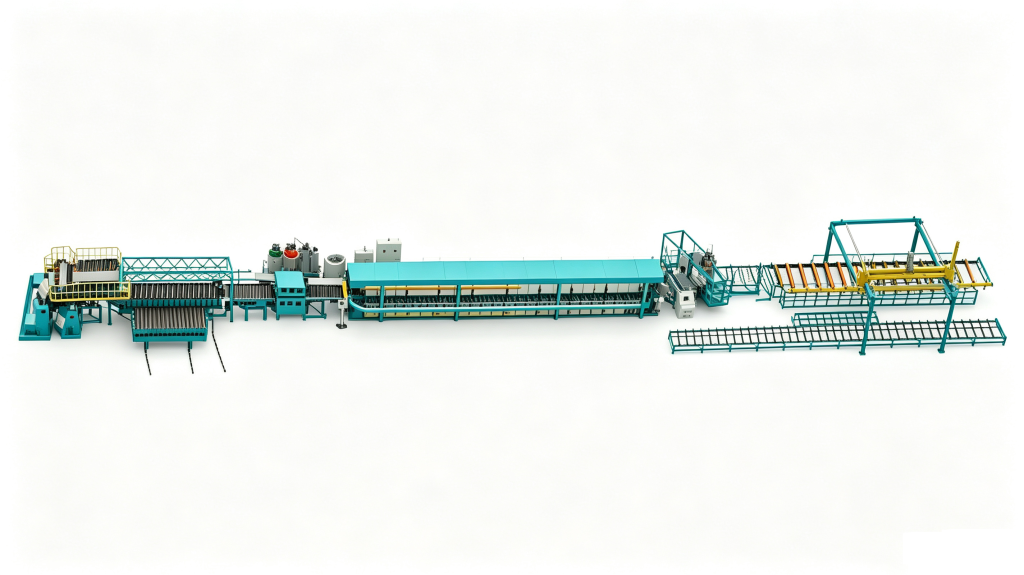

Tank insulation equipment is usually bought to solve a heat loss figure, but the choice between spraying foam onto the shell and injecting it into a jacket cavity is decided earlier, in the geometry and the fixture. Spraying is an access and surface problem: the gun has to see the steel, and the foam has to bond to it. Jacket injection is a mold-filling problem: the foam has to reach the far end of a closed gap before it sets. Both routes can hit the same thermal target on a drawing. They do not fail in the same way, and they do not ask the same thing of your workshop.
Why Constrained Foam Behaves Differently From Free-Rise Foam
Sprayed foam rises against air. One face touches the steel, the other stays free, and the material settles at whatever density the formulation and the gun output produce. That is the free-rise density, and it is what a spray grade quotation is normally describing.
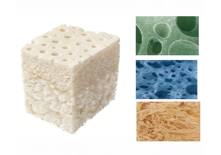
Foam injected into a jacket has nowhere to go. It rises inside a closed gap, presses against the tank shell and the jacket at the same time, and packs. The same formulation ends up denser in place than it would in a free-rise cup, and the density is rarely uniform: foam near the injection port usually carries the highest pack, while the far end of the flow path carries the lowest, because the front loses blowing gas and heat as it travels. A cut section from a jacket-filled tank normally shows that gradient. What is not normal is a gradient that crosses into the range where the foam stops being closed cell.
Two consequences follow. The first is that density numbers are not comparable across routes unless the basis is stated. A density quoted for a spray grade and an in-place density measured on a cut core (ASTM D1622 [1]) describe different things: one is free rise, the other is packed. When a supplier quotes a density, ask which one it is.
The second is that jacket injection produces a bonded sandwich and spraying does not. Foam bonded to both the shell and an outer jacket adds stiffness to the assembly, which is one reason thin-wall tanks often use a jacket instead of sprayed foam plus separate cladding. Sprayed foam bonded to one face still insulates, but it contributes far less structurally, and the free skin on the outside is easily damaged during cladding work.
The mechanism also predicts where each route fails. Spray failures usually start at the interface: dust, moisture, cold steel, or a pass applied too thick before the previous one had set. Jacket failures usually start at the far end of the fill: a short shot, a trapped air pocket, or a jacket that bulged because the shot was sized for the volume and not for the pressure.
| Point of comparison | Spray application | Jacket injection | How the difference is established |
|---|---|---|---|
| Foam constraint | Rises against air, one face bonded | Rises in a closed gap, both faces bonded | Cut section from each route |
| In-place density | Close to the free-rise figure | Above free rise, with a gradient along the flow path | ASTM D1622 [1] on cores from agreed positions |
| Structural effect | Insulation only | Bonded sandwich adds stiffness to thin walls | Supplier claim until panels or sections are tested |
| Access requirement | Line of sight and rotation | Ports and vents in a closed cavity | Walk the gun path or the fill path on the drawing |
| Dominant failure | Delamination at the steel interface | Short fill or void at the far end | Pull-off test or sectioned trial |
| Foam grade | Spray grade to ASTM C1029 [2] | Cavity filling grade with full reaction data | Supplier data sheet plus trial |
Treat the last column as the only part of that table you can act on immediately. The rest describes mechanisms; the right-hand column is what you can measure before money changes hands.
Which Tank Shapes Actually Suit Spray Application
Spray needs three things: a surface the gun can reach, a surface the foam can bond to, and an environment that keeps overspray away from people and from finished parts.
Line of sight is the first filter. A cylindrical tank on a turning roll is the easy case, because rotation brings every point under the gun at a workable angle. A rectangular tank with internal baffles, a small-diameter vessel, or a tank with closely spaced nozzles and manways is harder. Each obstruction creates a shadow where the spray angle is wrong, and a shallow angle produces a thin pass that may not bond. The practical test is to walk the gun path on the drawing before pricing the job and mark every point that cannot be sprayed at close to a right angle.
Surface condition is the second filter. Foam adheres to clean, dry, sound steel. Mill scale, cutting fluid, rust and condensation all reduce the bond, and a delaminated layer is difficult to repair without cutting back the foam, which means the cost of surface preparation belongs in the process cost, not in an optional line item. Substrate temperature matters as much as cleanliness: the steel should sit above the dew point of the surrounding air with a margin, because condensation forming while the foam rises reacts with the isocyanate and leaves a weak, brittle interface.
Small vessels often fail this filter outright. On a 300 mm tank, the gun cannot be presented at a useful distance, overspray fills the workspace, and someone has to handle the part while it is being coated. Injection into a jacket or a split mold is usually the practical route at that scale.
The third filter is the workshop itself. Spraying produces aerosol and isocyanate mist that has to be extracted, and the operator needs supplied-air respiratory protection. If there is no booth and no extraction, the honest options are to build one, to subcontract the coating, or to move to jacket injection, which releases far less airborne material because the foam is contained.
One condition that gets overlooked: spray thickness is built in passes, and each pass has to be thin enough to stay stable while it rises. Too much material at once produces sag, unnecessary exotherm in the core, and a density that varies around the tank. Pass count is a genuine scheduling input, and it is the main reason a sprayed tank takes a longer route through the shop than a jacketed one.
Sprayed tank insulation uses the same two-component chemistry as any other SPF work, so the material side of the decision is separate from the gun path. <What Is Spray Polyurethane Foam Composition And Application> covers its composition and where the material is applied.

What Jacket Injection Demands From Cavity Design
Jacket injection turns insulation into a mold-filling job, and mold filling is governed by flow length, venting and pressure.
The gap sets the flow. A very thin annulus restricts the foam front: the material has to shear through a narrow section, loses velocity, and the front can stall before it reaches the vent. A very thick annulus fills more easily but consumes more material and gives the foam room to rise unevenly, which steepens the density gradient. The workable range depends on the foam’s cream and gel times and on the injection rate, which is why gap and foam grade have to be selected together rather than in sequence.
How quickly a front advances through a narrow gap depends on the rise profile, not only on the machine’s output. <The Role Of Rise Time In Polyurethane Foaming> covers how rise time is measured and where it sits in the foaming sequence.
Fill points and vents are the part most often under-designed. Each injection port fills a limited length of cavity; beyond that length the front cools, the driving force drops, and the end of the cavity stays empty. In practice you place ports so that no point in the cavity is farther from a port than the distance your own trial proves, and you put a vent at every high point and at the far end of every flow path. A witness hole at the last point to fill is the simplest confirmation available: when foam extrudes from it, the front arrived.
The shot has to be calculated, not estimated. The arithmetic is geometry plus a target in-place density:
Cavity volume per metre of height (m³) = 0.785 x (jacket ID² – tank OD²), with diameters in metres.
For a 1,000 mm tank inside a 1,060 mm jacket, the annulus area is about 0.097 m², so one metre of height holds roughly 0.097 m³. At a target in-place density of 40 kg/m³ agreed with your foam supplier, that is about 3.9 kg per metre of height; at 45 kg/m³ it is about 4.4 kg. End caps, domes and nozzles are counted separately, and vent loss is added on top. This is also where a machine rated in grams per second earns its price: the whole shot has to be delivered before the front sets, so shot rate matters more than continuous output.
Jacket strength is the last constraint and the one that damages hardware. The foam exerts pressure while it packs. A thin-gauge jacket can bulge permanently, and a jacket that bulges changes the cavity for every part made after it. Measure the jacket diameter before and after a fill; a permanent increase means the jacket is under-specified or the shot is oversized.
Comparing Density, Adhesion and Heat Loss on Equal Terms
Three measurements decide whether either route performed, and all three are easy to quote in a way that hides the answer.
Density. Apparent density on a cut sample is covered by ASTM D1622 [1]. The number is only meaningful if the sample positions are agreed in advance, because a single core from the middle of a jacket-filled tank says nothing about the ends.
Closed-cell content. Measured to ISO 4590 [5], this supports a claim about retained cell gas and therefore about thermal performance over time. It does not prove the foam bonded to the steel, and it does not prove the cavity is full.
Thermal conductivity. Quote it with a mean temperature and a condition, initial or aged, measured to ASTM C518 [4]. An initial value and an aged value can differ substantially because the cell gas changes with time. Two suppliers quoting at different mean temperatures have not given you comparable figures, even if the digits look similar.
Adhesion. For sprayed foam, a pull-off test with a portable adhesion tester (ASTM D4541 [3]) on a panel sprayed with the same preparation gives a number you can compare between contractors and between batches. For jacket injection, adhesion is checked by cutting a strip from the interface and seeing where it separates: clean release from the steel means the interface failed, while foam tearing internally means the bond exceeded the foam’s own strength.
If the tank stores potable hot water, standing heat loss may be governed by the specification you are building to, for example EN 12897 [6], so work from the current edition rather than a remembered figure. Whatever the route, insulation is only as good as its continuity: fittings, manways, support saddles and pipe stubs form thermal bridges, and sprayed foam can be worked around them while a jacket has to be designed around them. The useful check is a hot-fill test at working temperature with a thermal image of the outer surface, which shows the bridge as a hot band rather than as an argument.
How Each Route Reshapes Line Layout and Output
The bottleneck sits in different places, and that difference usually decides more than the machine price.
Spray consumes hours before the gun is switched on: masking, surface preparation, dew point checks. Then come the passes with a wait between them, then cure, then cladding. The gun is busy for part of the cycle, and labor is busy for most of it. Jacket injection consumes hours in jacket fabrication and fit-up, then a short fill, then cure and handling. The jacket replaces the cladding, so a finishing step disappears from the route, which is the part of the comparison that a per-kilogram material price hides.
Handling changes with it. Spray needs a booth or tent sized for the largest tank plus turning equipment. Jacket injection needs space to store and fit jackets and lifting capacity for a heavier assembly at every step after filling.
Skill distribution changes too. Spray quality depends heavily on the operator: a good one lays uniform passes, a poor one leaves thin shadowed areas that fail later. Jacket injection moves the skill into fixture design and shot parameters, which are repeatable once set. For a plant with high staff turnover, that shift matters.
Changeover is the other hidden cost. A new tank diameter needs a new gun path but no new hardware, so mixed sizes are cheap to spray. A new tank diameter in a jacketed line needs a new jacket, which is fabrication cost and lead time, and a jacket change is a real item on the schedule. High-volume repeat sizes amortise jacket tooling quickly; one-off sizes do not.
Output planning is arithmetic you can do with your own stopwatch. Time one spray cycle end to end, masking through cladding. Time one jacket cycle, fit-up through handling. Divide available hours by the longer of machine time or labor time in each route, because that is what actually sets the rate.

What to Write Into the Machine Specification
Two different machine classes are involved, and they are specified in different units. A spray unit is rated by flow and pressure at the gun. A cavity filling unit is rated by shot rate in grams per second, ratio accuracy and mixing pressure.
| Specification | Spray unit for cold storage duty (HF-SP-03) | Jacket filling metering unit (HF-HPM-1A1B-PipeInsulation) |
|---|---|---|
| Maximum output | 10 kg/min at 110 bar; 5 kg/min at 160 bar | 80 to 1,500 g/s, roughly 4.8 to 90 kg/min |
| Working pressure | 160 bar maximum at the gun | 10 to 18 MPa mixing pressure, about 100 to 180 bar |
| Drive and mixing | Hydraulic drive, two-component impingement spray | High-pressure metering, mixing head 8,000 to 14,000 rpm |
| Material heating | 6 kW heater, insulated hose up to 93 m | Material temperature control 20 to 45 C |
| Tank volume | Two material tanks | 100 L and 150 L per tank |
| Electrical load | 3-phase 400 V supply | 5.5 to 7.5 kW |
Those figures come from the equipment data for the two models named, and they illustrate why the units differ rather than which machine is better.
Ratio accuracy deserves its own line in any inquiry. A stated dosing accuracy of plus or minus 0.3 percent of full range is the kind of figure that separates a metering machine from a proportioning unit, because a small ratio error shifts both density and strength at the same time, and it does so silently. Ask for the accuracy basis and the test method, not just the number.
Hose and material heating matter for a reason that is easy to miss: viscosity depends on temperature, and a cold hose changes the pressure drop and the effective ratio before the material reaches the mixing head. For spray, heating also affects atomization and therefore the adhesion of the first pass.
Tank size should be matched to daily consumption, not to the biggest option available. A large tank that sits half full for a week exposes the material to moisture and aging, and refills during a production run interrupt the cycle. On the spray side, confirm the maximum heated hose length against the largest tank you intend to coat, because reach defines which tanks the machine can serve at all.
Cavity filling starts with a shot size you can defend on paper before the first trial part is poured. <How To Calculate Shot Weight In Polyurethane> covers how shot weight is calculated from cavity volume and target density.
How to Qualify the Route Before You Order Equipment
Trials are where the route decision becomes evidence, and the trial has to match the production geometry.
Running a cavity injection trial
Build a short section of the real cavity: same gap, same jacket material, same port and vent positions. Inject with the production foam lot and the production machine settings. Cut it open at the injection end, the middle and the far end. Record density at each position, note where voids sit and how large they are, and check whether the foam bonded to both faces. A trial run at a different gap proves nothing about the real one, which is why welding distortion in a production jacket is itself a variable worth measuring at several points around the circumference.
Running a spray trial
Spray a test panel of the same steel with the same surface preparation, the same substrate temperature and the same pass thickness. Cut cores for thickness and density, run a pull-off test for adhesion, and inspect the interface for a shiny detachment line, which is the signature of a bond that never formed.
When each route is the wrong choice
Do not choose spraying when the tank cannot be rotated or reached at a workable angle, when there is no extraction and no plan to install it, when substrate and ambient conditions cannot be held long enough for the passes to set, or when the finished surface will be handled heavily before cladding goes on.
Do not choose jacket injection when the installation leaves no room for a jacket, when the batch is a single unit and jacket fabrication cannot be recovered, when wall thickness cannot take fill pressure without distortion, or when continuous service temperature exceeds what the selected foam grade tolerates. That last point needs the grade’s declared continuous service temperature compared against your maximum stored temperature plus a margin, not a general assumption about rigid foam.
One judgement I would underline: if a trial shows voids at the far end, the fix is a port or vent change or a faster reacting foam, not a larger shot. Oversizing the shot raises pressure on the jacket and density near the port without filling the end, and it turns a fill problem into a distortion problem.
Before requesting a quotation, put these on one page:
| Field | What to provide | Failure it prevents |
|---|---|---|
| Tank and jacket geometry | OD, jacket ID, annulus in mm, end cap shape | A shot sized for the wrong volume |
| Foam grade and reaction data | Cream time, gel time, free-rise density, target in-place density | A front that stalls before the vent |
| Port and vent plan | Number and position of each, flow length per port | Voids at the far end and at the top |
| Substrate condition | Surface preparation, steel temperature, dew point margin | Delamination at the interface |
| Test method and sample positions | Density and closed-cell standards, sample locations, pull-off method | Numbers that cannot be compared |
| Acceptance and change control | Void limit, density range, notification before a formulation change | A silent shift after approval |

Send Your Tank Geometry Before You Choose a Machine
The route usually becomes obvious once the geometry is on the table: a 300 mm vessel with six nozzles is an injection job, while a 3 m open cylinder may suit either route depending on whether you already have extraction. What cannot be settled from a catalogue is how much shot your cavity needs, how many ports it takes to fill it, and whether your jacket can hold the fill pressure.
Send the tank drawing with the jacket inner diameter and the annular gap, the foam grade with its cream and gel times, your target in-place density, the maximum service temperature and the cycle time you need per tank. That is enough to size the shot, propose a port and vent layout, and say whether the job needs a spray unit or a high-pressure metering machine.
Haifeng Polyurethane Machinery builds both classes of equipment and quotes against your geometry rather than against a nominal output figure. Email Info@chinahaifeng.com or WhatsApp 86 13566296633 with the drawing, and the reply will state the shot size, the port plan and the machine configuration that match them.
FAQ
Can you spray foam onto a tank that already has its outer jacket?
Not in any practical sense. Spray needs the surface visible to the gun, and a closed jacket removes that access. If the jacket is removable or split, the sensible sequence is to spray the shell, let the foam cure, then fit the jacket. If the jacket is welded in place, the job becomes cavity injection, which needs fill ports, vents and a shot size worked out from the annulus. Field retrofits can be injected through a port, but the ambient conditions at the plant differ from the workshop, so the trial data from the factory does not transfer without a fresh check.
How thick should the insulation be on a hot water tank?
Start from the allowable standing heat loss in the specification you are building to, then convert through the tank surface area and the foam’s quoted conductivity at the relevant mean temperature. Add thickness where fittings and supports create bridges, because those areas lose more heat per unit of area than the plain shell. The answer also has to fit the jacket diameter and the installation envelope. Any single thickness quoted without the stored water temperature, the ambient condition and the target loss figure is a guess dressed as a recommendation.
Why does injected foam leave voids at the top of a cavity?
Air has to leave at the same rate the foam arrives, and the top of a cavity is normally the last place both happen. If the vent is missing, blocked or too small, the rising foam compresses trapped air and stalls short of the top. A front that has cooled and slowed produces the same result. The fixes are a vent at the highest point, a shorter flow length per port, or a foam with a faster cream and gel, and each of those is verified on a sectioned trial rather than by adding material.
Is sprayed foam or injected foam cheaper per tank?
It depends on whether the jacket replaces cladding, on your labor rate for masking and surface preparation, and on batch size. A repeated tank size amortises jacket fabrication quickly and removes the cladding step, so the installed cost per unit usually falls as volume rises. A one-off large tank with open access, an existing booth and a low labor rate can favor spraying, provided the pass count still fits your schedule. Compare the two complete routes, including cure time and rework risk, rather than the foam cost per kilogram.
References
[1] ASTM D1622/D1622M, “Standard Test Method for Apparent Density of Rigid Cellular Plastics,” ASTM International.
[2] ASTM C1029/C1029M, “Standard Specification for Spray-Applied Rigid Cellular Polyurethane Thermal Insulation,” ASTM International.
[3] ASTM D4541/D4541M, “Standard Test Method for Pull-Off Strength of Coatings Using Portable Adhesion Testers,” ASTM International.
[4] ASTM C518, “Standard Test Method for Steady-State Thermal Transmission Properties by Means of the Heat Flow Meter Apparatus,” ASTM International.
[5] ISO 4590, “Rigid cellular plastics — Determination of the volume percentage of open cells and of closed cells,” ISO.
[6] EN 12897, “Water supply — Specification for indirectly heated unvented (closed) storage water heaters,” CEN.
If you’re interested, check out these related articles:
SRIM Explained Structural Reaction Injection Molding Basics
What Is Spray Polyurethane Foam Composition And Application
Shore A Vs Shore D Hardness In Polyurethane
RRIM Vs RIM Which Process Suits Your Structural Part
How To Calculate Shot Weight In Polyurethane