Semi-rigid polyurethane foam sits between flexible seating foam and rigid insulation board, and that middle position creates most of the confusion in part design. In production terms, it is a microcellular or partially crosslinked polyurethane system with enough open or closed cell structure to compress under load while still recovering most of its shape. I have seen shops order a flexible foam system and then chase hardness for weeks because the part needed semi-rigid behavior instead. Getting the classification wrong changes density, demold time, and the metering setup on the foaming machine.
What Defines Semi-Rigid Polyurethane Foam?
Semi-rigid polyurethane foam is best defined by what it does under load, not by a single density number. A part that compresses firmly and returns most of the way without bottoming out is behaving as semi-rigid. The chemistry behind that behavior usually involves a moderate crosslink density in the polymer network. Too little crosslinking produces flexible foam that collapses under cycle loading. Too much produces a hard board with almost no recovery. The useful middle ground uses polyether or polyester polyols with a branching level high enough to hold cell shape but low enough for controlled deformation.
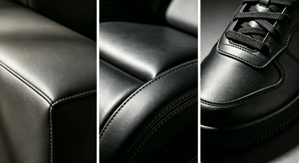
This is not a narrow product category. It includes energy-absorbing automotive pads, rail fastening cushions, shoe midsoles, armrests, and industrial gaskets. Most of these parts are molded, not slabstock, because the part geometry and skin layer matter as much as the foam itself. In mold filling, the formulation needs to flow far enough to pack thin sections without blowing the mold open. That places unusual demands on the mixing head and metering system.
A common reference point is hardness. Many semi-rigid parts land between Shore A 40 and Shore A 80, but that range shifts with density, cell size, and skin thickness. Two parts with the same Shore A reading can behave differently in fatigue if one has a dense molded skin and the other is a cut sample from a larger block. I usually ask for the full part drawing and the load case before recommending a hardness target.
How Does Semi-Rigid Polyurethane Foam Differ From Flexible and Rigid Foam?
The difference is not just density. It is how the cell walls respond after compression. Flexible foam has mostly open cells and low resistance to airflow. Rigid foam has a high closed-cell content and resists deformation. Semi-rigid foam sits between the two, often with a controlled mix of open and closed cells plus enough polymer strength to recover after repeated loading.
| Property | Flexible Foam | Semi-Rigid Foam | Rigid Foam |
|---|---|---|---|
| Typical density | 15 to 80 kg/m3 | 80 to 400 kg/m3 | 30 to 200 kg/m3 |
| Cell structure | Mostly open | Mixed open and closed | Mostly closed |
| Compression behavior | Soft, high recovery | Firm, partial recovery | Hard, little recovery |
| Common molded parts | Seat cushions, armrests | Rail pads, buffers, shoe midsoles | Insulation panels, structural cores |
| Main equipment concern | Venting and even rise | Metering accuracy and mold pressure | Fast injection and pack pressure |
Density ranges overlap because formulation and part geometry push the final behavior more than the raw density number. A 120 kg/m3 semi-rigid rail pad can feel harder than a 120 kg/m3 rigid foam block if the rail pad has a thick molded skin. For this reason, I treat the table above as a starting filter, not a specification.
When a production manager tells me a part is “hard but not rigid,” I look at the load case first. Is the part absorbing impact once or cycling thousands of times? Is the buyer specifying hardness because a drawing says so, or because the previous part failed in service? Those answers determine whether the chemistry should lean toward open-cell recovery or closed-cell energy absorption.
What Processing Conditions Control Semi-Rigid Foam Density and Hardness?
Four process variables move semi-rigid foam behavior more than most formulation tweaks: component ratio, mold temperature, mixing pressure, and fill rate. Ratio error is the most damaging because it changes density, hardness, and surface quality at the same time. A one percentage point deviation in the component ratio can shift final foam density by more than 3 kg/m3. For thin-wall molded parts, that is enough to create soft spots near the end of fill.
On one automotive seat cushion line, manual mixing caused a ratio error of plus or minus 4 percent. The defect rate sat at 11 percent and raw material waste at 14 percent. Moving the line to high-pressure foaming machines with servo metering and a PLC traceability system cut the defect rate from 11 percent to 1.5 percent and shortened the forming cycle from 40 minutes to 25 minutes. The chemistry did not change at first. The control did.
Mold temperature matters because the semi-rigid skin forms against the mold surface. If the mold is too cold, the surface stays thin and the part can show flow lines or pinholes. If the mold is too hot, the blowing reaction outruns the gel reaction and the part can collapse or shrink after demold. We normally hold mold temperature between 40 and 80 degrees Celsius for automotive buffer blocks and microcellular parts, with the exact setpoint tied to part thickness and cycle time.
Mixing pressure and fill rate decide whether the foam structure stays uniform across the cavity. Low-pressure machines work for smaller shots and lower-viscosity systems, but high-pressure impingement mixing gives a finer cell structure and better surface on parts with long flow paths. The tradeoff is higher equipment cost and more attention to hydraulic and temperature stability.
If your program uses a semi-rigid part with a Shore A target above 65 or a density below 120 kg/m3, it is worth confirming the metering accuracy and mold temperature control before finalizing your BOM. Send your current part drawing and target hardness to info@chinahaifeng.com or WhatsApp: 86 13566296633, and we can check where the process is likely to drift first.
Why Does Semi-Rigid Foam Work Well in Automotive and Rail Components?
Semi-rigid polyurethane foam earns its place in automotive and rail parts because it absorbs energy without becoming a solid part. A suspension buffer pad needs to compress under shock load, return to shape, and survive thousands of cycles without cracking. A rail pad must hold rail fastening geometry under repeated wheel loads and retain enough resilience at low temperatures. Both applications depend on controlled cell collapse and polymer recovery.
Rail pads show why process control matters as much as formulation. A manufacturer was producing rail pads at below 80 percent qualification with four operators per line. Daily output stayed around 80 pads. Moving to a compact split-modular rotary disc line with a precision pouring nozzle raised qualification to above 99 percent and daily output to over 200 pads. Labor dropped from four operators to two. The material was not the bottleneck. Consistent mold filling was.
Automotive buffer blocks have similar sensitivities. When tolerance requirements move from plus or minus 1.2 millimeters to plus or minus 0.3 millimeters, the foaming machine needs closed-loop ratio control and stable mold clamping. A high-pressure machine with a 20-station rotary mold carrier can hold that tolerance while cutting defect rates from 5.2 percent to 2 percent. Those gains come from repeatable shot weight and even temperature, not from switching to an expensive exotic polyol.
This is where semi-rigid processing rewards a line-level view. The part, mold, metering unit, and curing schedule form one system. Changing one variable without checking the others usually moves the problem instead of solving it. I have seen shops chase a hardness complaint through three polyol suppliers when the real issue was a mold temperature swing of 6 degrees Celsius between morning and afternoon shifts.
If your current semi-rigid parts show density drift, surface pinholes, or hardness variation that forces sorting, the problem is usually not the polyol alone. It is the way the machine meters, mixes, and fills the mold. Haifeng Polyurethane Machinery has used high-pressure metering and closed-loop mold temperature control so production teams hold tighter part specs without replacing the whole workshop. Send your part drawing, target density, and current scrap rate to info@chinahaifeng.com or WhatsApp: 86 13566296633, and we will identify which process parameter is driving the variation.
What Do Production Teams Ask About Semi-Rigid Polyurethane Foam?
How is semi-rigid foam different from microcellular polyurethane?
Semi-rigid foam is a broader processing category. Microcellular polyurethane is one common route to it. A microcellular part has very small, evenly distributed cells and a dense skin, which produces the controlled firmness and good surface that many semi-rigid applications require. Not every semi-rigid foam is microcellular, but most molded technical parts are. If a drawing calls out microcellular polyurethane, the equipment and tooling need to handle higher mold pressure and tighter shot weight control than standard flexible foam.
What hardness range should I specify for a semi-rigid part?
Hardness is the first number buyers ask for, but it is rarely the number that solves the application. Most semi-rigid molded parts sit between Shore A 40 and Shore A 80. The better spec combines hardness with density, load-deflection, compression set, and the actual service temperature. A rail pad at Shore A 55 can pass a hardness check and still fail in service if compression set is too high or low-temperature recovery is poor. I would specify hardness only after the load case and fatigue requirement are clear.
Can I run semi-rigid foam on a low-pressure machine?
It depends on shot weight, viscosity, and how tight the density tolerance is. Low-pressure machines work for smaller shots, moderate viscosity, and parts where a slightly coarser cell structure is acceptable. High-pressure impingement mixing becomes the better choice when the part has a long flow path, a visible molded surface, or a density tolerance below plus or minus 2 percent. The machine selection should follow the mold and part, not the other way around.
Why does my semi-rigid part shrink after demold?
In lines I have worked on, post-demold shrinkage usually traces back to two places: the mold temperature profile and the isocyanate index. If the surface cures too fast while the core is still reacting, the part pulls inward as it cools. A low index can also leave the network too weak to hold dimensions. Before changing the polyol, I would record demold hardness at several points and map mold temperature across the cavity. Share your part drawing, current hardness, and mold layout with us and we can check whether the process or the formulation is driving the dimensional change.