
Two samples taken from the same batch can read 28 kg/m³ and 55 kg/m³ on the bench — and both measurements can be correct. The difference is not the formulation. It is what the foam was allowed to do while it reacted. One sample rose freely in an open cup. The other was poured into a filled, vented mold. That single condition gap is the difference between free-rise density and molded density, and it is where a surprising number of density specifications quietly fall apart.
The problem usually shows up later: a part is quoted at free-rise density, the shot weight is calculated from the wrong number, and the first production run comes out underfilled, overpacked, or heavier than expected. Understanding the two densities as separate controls — not interchangeable values — is the fastest way to stop that loop.

What Free-Rise Density Actually Measures
Free-rise density is the density a polyurethane formulation reaches when it expands without a closed cavity constraining it. In practice, that means a cup test: a known mass of reacting material is poured into an open container large enough for the foam to rise, gel, and cure without hitting a lid or packed walls.
The measurement itself follows the same principle as any cellular-plastic density determination: mass divided by occupied volume, with flexible and rigid materials reported in kilograms per cubic metre according to their respective test methods [1][2]. For flexible foam, the core is cut, conditioned, and weighed; for rigid systems, the sample geometry or displacement volume is used with the same mass balance [1][3].
What this number tells you is mostly about the formulation, not the part. Water level, blowing agent load, surfactant balance, material temperature, and mix energy all shift the rise height, and therefore the free-rise density. If the same grams of material rise taller, the density reads lower. That is why free-rise density works well as a repeatability check on incoming material and a baseline for process work — but it is not the final part density.
Free-rise density is the result of how far and how fast the foam expands before gel. The Role Of Rise Time In Polyurethane Foaming covers how rise time, gel time and mix energy set that open-cup number.

What Changes When Foam Meets a Mold
The moment the same formulation enters a mold, the reaction faces walls. Expansion is no longer free, so gas pressure builds inside the cavity, cells are compressed and refined near the surface, and a denser skin forms where the mix contacts the mold. The result is an average part density higher than the open-cup value — sometimes modestly, sometimes by a large margin.
Molded foams are tested under the same standards family as free-rise material, but the sample is now cut or taken from a finished part, so skin, core, and any density gradient are all included in the measurement [2][3]. A molded flexible part shows a skin-to-core difference driven by mold temperature, venting, and how full the cavity was when the material gelled. A rigid molded panel behaves the same way, with the added variable of packing pressure during rise.
This is where free-rise and molded density stop being substitutes. Free-rise tells you what the chemistry wants to do. Molded density tells you what the combination of chemistry, shot weight, cavity volume, and venting actually produced.
Molded density is only half the story — the part must hold that number after demold and cooling. Causes Of Shrinkage In Polyurethane Foam How To Control It covers how shrinkage shifts the final dimensions and apparent density of a molded part.
Overpack Ratio: The Number That Connects Them
The cleanest way to relate the two values is the overpack ratio: molded density divided by free-rise density. A formulation with a 30 kg/m³ free-rise reading that produces a 45 kg/m³ molded part has an overpack of 1.5.
In practice, the ratio depends heavily on part type. Flexible molded cushions commonly run modest overpack levels, while microcellular elastomers and integral-skin parts can carry far higher ratios because the dense skin and compressed core represent a larger share of part volume. If the ratio sits barely above 1.0, the mold is acting close to an open container and offering little packing benefit; if it climbs too high, cycle time, venting, flash, and demold behavior all start to change.
The overpack ratio should be treated as an engineering input rather than a fixed rule of thumb. It is set by the cavity size, the shot weight, the vent design, and how early the material gels against the walls.

Free-Rise vs. Molded Density at a Glance
| Factor | Free-rise density | Molded density |
|---|---|---|
| Definition | Density of foam expanded in an open container | Average density after filling a closed or vented mold |
| Primary driver | Blowing load, water content, surfactant, material temperature | Shot weight vs. cavity volume, overpack, skin formation |
| Typical flexible range | ~20–60 kg/m³ | ~35–70 kg/m³ at roughly 1.1–1.6 overpack |
| Typical rigid range | ~30–50 kg/m³ | ~35–55 kg/m³ in panels with moderate packing |
| Uniformity | Vertical gradient develops as rise slows | Skin-to-core gradient governed by mold temperature and packing |
| Specification role | Formulation fingerprint and quality-control baseline | Part quality target and shot-weight reference |
| Common failure | Reading quoted for a molded part it does not represent | Underfill voids, overpack flashing, long demold times |
The ranges above are field-typical rather than universal; the correct values for a specific system come from its own cup test, mold trial, and target part section.
How to Set a Molded Density Target in Practice
The calculation flows from the part backward. Once the target molded density is fixed, shot weight follows from the cavity volume:
shot weight (g) = cavity volume (cm³) × target molded density (g/cm³) × (1 + process allowance)
For example, a 800 cm³ cavity at a 0.60 g/cm³ target needs roughly 480 g of material before a small allowance for flash and venting. The allowance is not decorative — underfilling leaves voids, while overfilling wastes material and lengthens demold.
Once the target molded density is locked, the next calculation is how much material actually enters the cavity. How To Calculate Shot Weight In Polyurethane covers shot weight, cavity volume, flash allowance and the corrections that keep real parts on target.
From there, density control becomes a process discipline. Venting must let air escape without letting too much material follow it. Mold temperature must stay stable enough that skin thickness does not wander. Metering accuracy must hold the shot weight within a window tight enough that the overpack ratio does not drift through the shift.
Pinpointing the Equipment Variables
When molded density drifts, the instinct is often to adjust the formulation. Before changing chemistry, it is worth checking whether the line can repeat the same shot at all. If the component ratio has shifted by even a small amount, the reaction speed changes, the rise behavior changes, and the molded density follows.
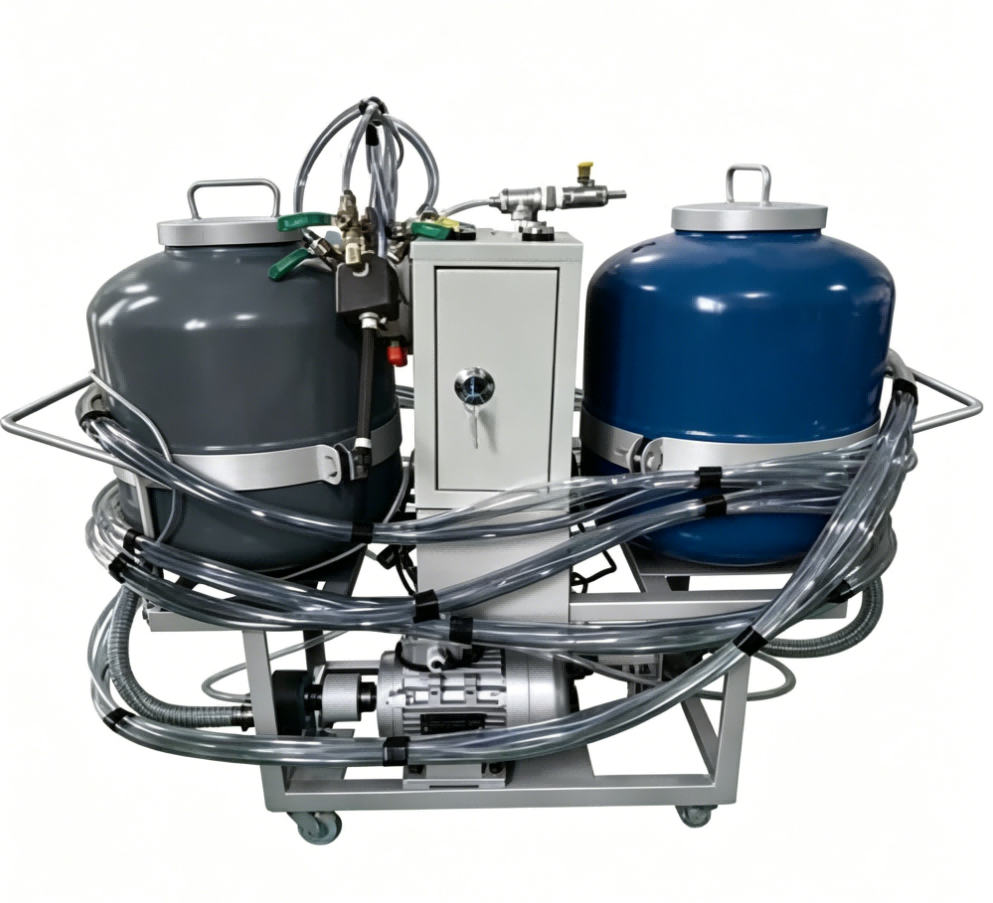
Temperature is the quiet multiplier. Material that arrives cooler or warmer than the setpoint changes viscosity, mixing quality, and reaction profile. The same shot mass can produce a different fill and a different skin-to-core distribution as the day warms up. On a molded rail-pad or sole line, holding shot weight within a few grams and metering deviation below ±0.3% is what turns a density window from a target into a repeatable number — that repeatability is the reason density is treated as a metering problem before it becomes a formulation problem.
If you are chasing a molded density window and the equipment drifts as the day warms up, start with the metering and shot-weight data rather than another additive. Send your target density, mold volume, cycle time, and current cup results to Info@chinahaifeng.com with a short note; the more context you can share, the sooner it becomes a line-specification question instead of a formulation guess.
Practical Checklist Before You Lock the Molded Density
- Record the free-rise cup density of the same batch you are molding.
- Confirm the cavity volume from the mold drawing, not from a nominal part volume.
- Calculate the required shot weight from cavity volume and target molded density.
- Add a measured allowance for flash, venting, and runner losses — then record the actual requirement.
- Set the overpack ratio deliberately and keep it stable across the shift.
- Verify metering accuracy at the operating throughput, not only in a calibration run.
- Check material and mold temperatures at the start, middle, and end of the run.
- Cut a molded part for a skin-to-core density check before releasing the line.
Spec the Line Around Your Molded Density Window
Production lines are often shortlisted on cycle time, but they hold their value on repeatability at a density. If the line cannot repeat a shot weight, the molded density will drift no matter how good the target is. A concise inquiry with the data below gets to the equipment question faster.
| Item to prepare | Notes |
|---|---|
| Target molded density | Include the tolerance window |
| Mold cavity volume and part mass | Needed for shot weight |
| Free-rise cup density of the current system | Baseline for overpack |
| Part type | Integral skin, microcellular, flexible, or rigid |
| Cycle time and daily output | Drives machine sizing and mold carrier layout |
| Current metering accuracy or symptom | Drift, flash, voids, weight spread |
Email: Info@chinahaifeng.com
WhatsApp: 86 13566296633
Frequently Asked Questions
Is molded density always higher than free-rise density?
In most filled-mold processes it is, because the cavity compresses the rising foam and forms a denser skin. A severely underfilled or highly vented mold can produce a part close to — or occasionally below — a well-foamed free-rise sample, but that is usually a symptom of incomplete fill rather than a design target.
How do I measure free-rise density in a cup test?
Pour a weighed amount of the mixed system into an open container sized so the foam can rise, gel, and cure without touching a lid or packed walls. After curing, cut a representative core, condition it, and calculate mass divided by occupied volume according to the applicable flexible or rigid foam standard [1][2][3].
What overpack ratio should I design for?
There is no single correct number for every part. Flexible molded cushions commonly run modest overpack, while microcellular and integral-skin parts carry substantially higher ratios because the dense skin contributes more to part volume. The ratio should come from a mold trial on the target geometry, not from a general table.
Does higher molded density mean harder foam?
Not directly. Hardness is set primarily by polymer structure, crosslink density, and cell geometry. Two systems can hold similar hardness at different densities, and density changes can shift firmness without changing Shore hardness in a predictable one-to-one way. The relationship depends on the formulation and part type.
Why do two plants get different molded densities from the same formulation?
Because the mold, venting, shot weight, temperature profile, and metering stability differ. Formulation determines the free-rise baseline, but the molded result is a process output — which is why the same chemistry can read differently on two different lines.
References
[1] ISO 845:2006, Cellular plastics and rubbers — Determination of apparent density. International Organization for Standardization.
[2] ASTM D3574-17, Standard Test Methods for Flexible Cellular Materials — Slab, Bonded, and Molded Urethane Foams. ASTM International.
[3] ASTM D1622-20, Standard Test Method for Apparent Density of Rigid Cellular Plastics. ASTM International.
If you’re interested, check out these related articles:
Causes Of Shrinkage In Polyurethane Foam How To Control It
SRIM Explained Structural Reaction Injection Molding Basics
The Role Of Rise Time In Polyurethane Foaming
How Polyurethane Rollers Are Made From Casting To Cure
Shore A Vs Shore D Hardness In Polyurethane