
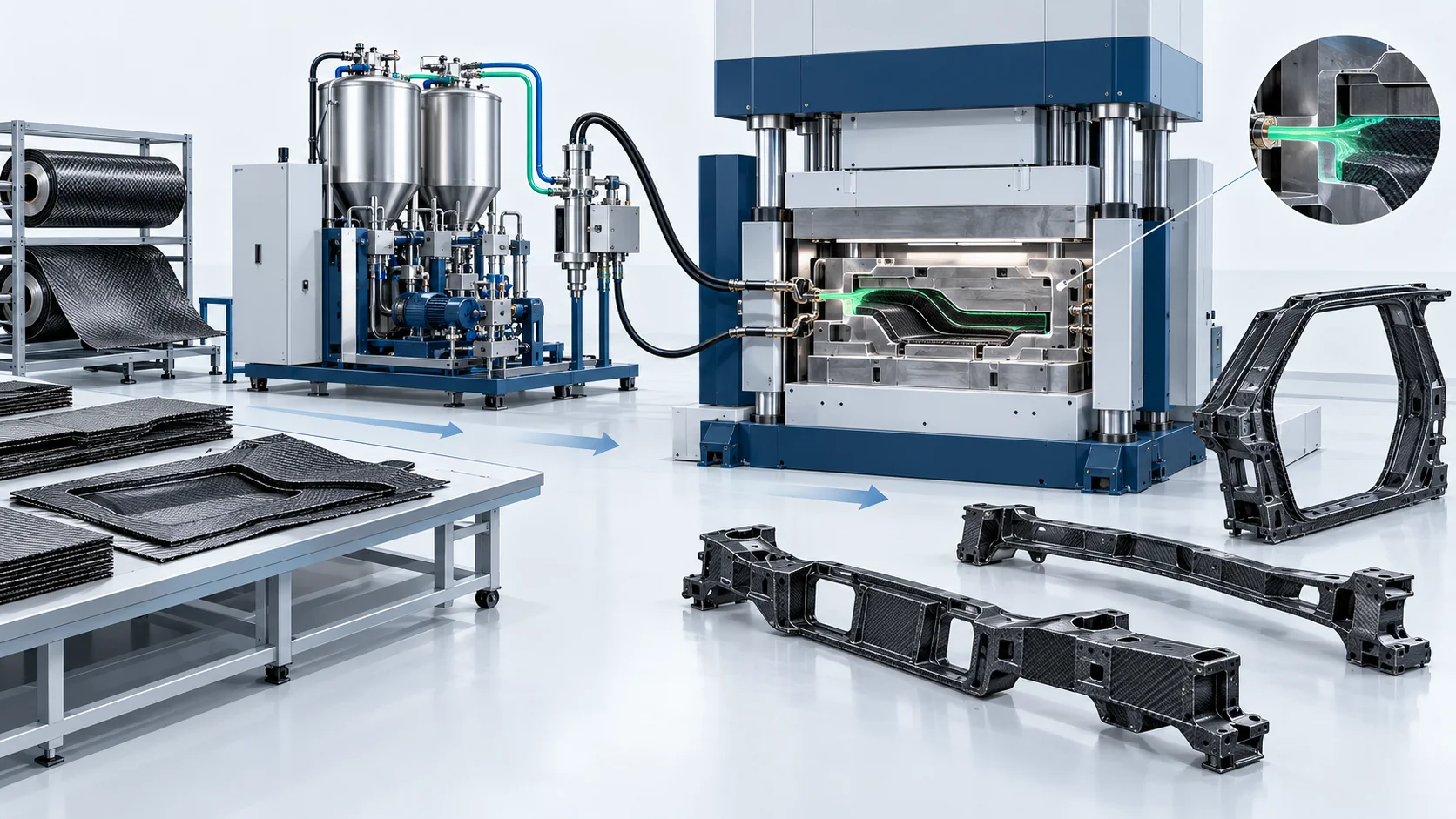
HP-RTM Machine | Carbon Fiber Body-in-White
HP-RTM metering and injection equipment for carbon-fiber B-pillars, roof crossmembers and floor beams, integrating ratio control, vacuum-assisted closed tooling and resin-specific cure management.
Dosing Accuracy
±0.5% application acceptance target
Tool Temperature
90–130°C resin-specific reference
Reinforcement
Carbon-fiber structural preforms
Reference Cycle
180–300 s; complete molding process
Product Overview
An application configuration for repeatable filling of structural carbon-fiber preforms.
The HF-RTM-HP150-BIW application configuration is a reactive resin metering and injection system for selected carbon-fiber body-in-white components. Typical targets include B-pillar reinforcements, roof crossmembers and floor beams produced from dry carbon-fiber preforms in matched, sealed tooling.
The configuration emphasizes component ratio control, shot sizing and filling of locally reinforced sections. The material system, preform architecture and gate layout determine the viable injection window. Tool evacuation and controlled press movements support filling while limiting preform displacement and air entrapment.
A fast-curing polyurethane or epoxy system is selected for the structural program. Tank conditioning and tool temperature have distinct roles: component temperature controls viscosity before mixing, while the mold thermal profile controls filling and cure. The supplied 90–130°C tool reference must be matched to the selected resin data, rather than used as a universal epoxy processing window.
The scope can include metering, the impingement head, vacuum, temperature control and a master PLC interface, with optional handling, press and tooling. Dimensional repeatability, residual cure, void content and laminate quality are assessed separately from crashworthiness, which is established through the component and vehicle validation program.
Explore the complete application solution · View the corresponding project case
Concept illustration — not a photograph of delivered equipment or a customer installation.
HP-RTM Application Workflow
Define the Structural Preform
Establish the fiber orientations, local reinforcement, insert locations and thickness zones from the structural part design. Prepare a repeatable dry-preform loading method.
Condition the Reactive Components
Condition the selected polyurethane or epoxy streams separately, set the resin-specific ratio and confirm viscosity and gel-time requirements before an injection recipe is released.
Close and Evacuate the Matched Tool
Load and locate the preform, close the mold to the prescribed position and evacuate the cavity. Interlock injection with press readiness, vacuum and tool temperature.
Meter, Mix and Inject the Resin
Use closed-loop component dosing and the impingement mixing head to deliver the specified resin shot. Coordinate flow, pressure ramp and gate sequence with the preform permeability and tool limits.
Control Structural Cure
Run the resin-specific mold thermal and press holding profile to develop demolding strength. The supplied reference complete molding window is 180–300 seconds, depending on geometry and formulation.
Trim and Qualify the Component
Trim or machine mounting interfaces, inspect dimensions and internal laminate quality, and verify cure and mechanical performance against the structural program acceptance plan.
Technical Specifications
Application engineering reference for the proposed configuration. Final equipment ratings and acceptance conditions are defined for the selected resin, preform, tool and press. Mixing pressure, injection-circuit pressure and mold-cavity pressure are specified separately. The reference cycle is a complete molding window, not injection time alone.
| Technical Parameter | HF-RTM-HP150-BIW |
|---|---|
| Components | 2 reactive components; separate additive dosing optional |
| Output Range (g/s) | Sized from part resin mass and qualified fill-time window |
| Mixing Ratio Range | Selected from resin supplier formulation; configured during application engineering |
| Ratio Accuracy | ±0.5% application acceptance target; operating point and method defined in the offer |
| Working Pressure | 30–150 bar reference injection-system range; mold-cavity limit specified separately |
| Target Components | Carbon-fiber B-pillars, roof crossmembers and floor beams |
| Compatible Resin Systems | Fast-curing polyurethane or epoxy; material-specific pump, seal and mixing-head configuration |
| Preform Design Reference | 50–60% fiber volume fraction in supplied brief; laminate property, not a machine output setting |
| Mold Temperature Reference | 90–130°C for the supplied application; final window follows the selected resin |
| Mold Vacuum Reference | <10 mbar absolute before injection; qualified with actual tool seals and venting |
| Reference Complete Molding Window | 180–300 s; geometry, resin, cure and handling dependent |
| Control System | PLC recipes, component ratio/flow records and press synchronization |
| Mixing Head | High-pressure impingement and mechanical self-cleaning; no dynamic stirring speed assumed |
| Optional Process Interface | Gap injection or compression sequence when supported by the qualified press and tool |
Built Around the Application Process
An application configuration for repeatable filling of structural carbon-fiber preforms.
Ratio-Controlled Reactive Dosing
A ±0.5% application acceptance target provides a basis for configuring and checking component metering at the agreed resin viscosity and operating flow.
Local Reinforcement Filling
Injection profiles and gate positions are selected for the transitions between thin sections, dense reinforcement zones and structural inserts.
Resin-Specific Temperature Recipes
Separate component conditioning and mold thermal recipes coordinate viscosity, fill time and cure without treating every resin system as interchangeable.
Tool and Press Synchronization
The control interface coordinates mold position, vacuum, shot permission and pressure release. Gap injection or compression sequences are options when the mold and press support them.
Shot Traceability for Structural Parts
Recipe and shot records connect material ratio, flow, temperature and cavity feedback with the production lot and the agreed quality inspection plan.
Compare Application Configurations
Compare resin injection configurations for suspension leaf springs, EV battery trays and carbon-fiber body structures.
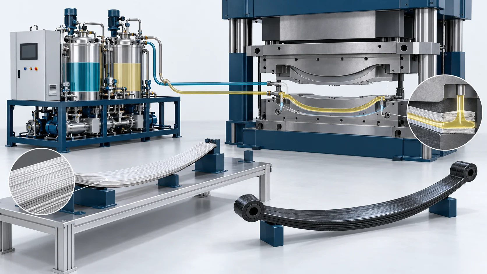
HP-RTM Machine | Composite Leaf Springs
High Pressure Polyurethane Machine
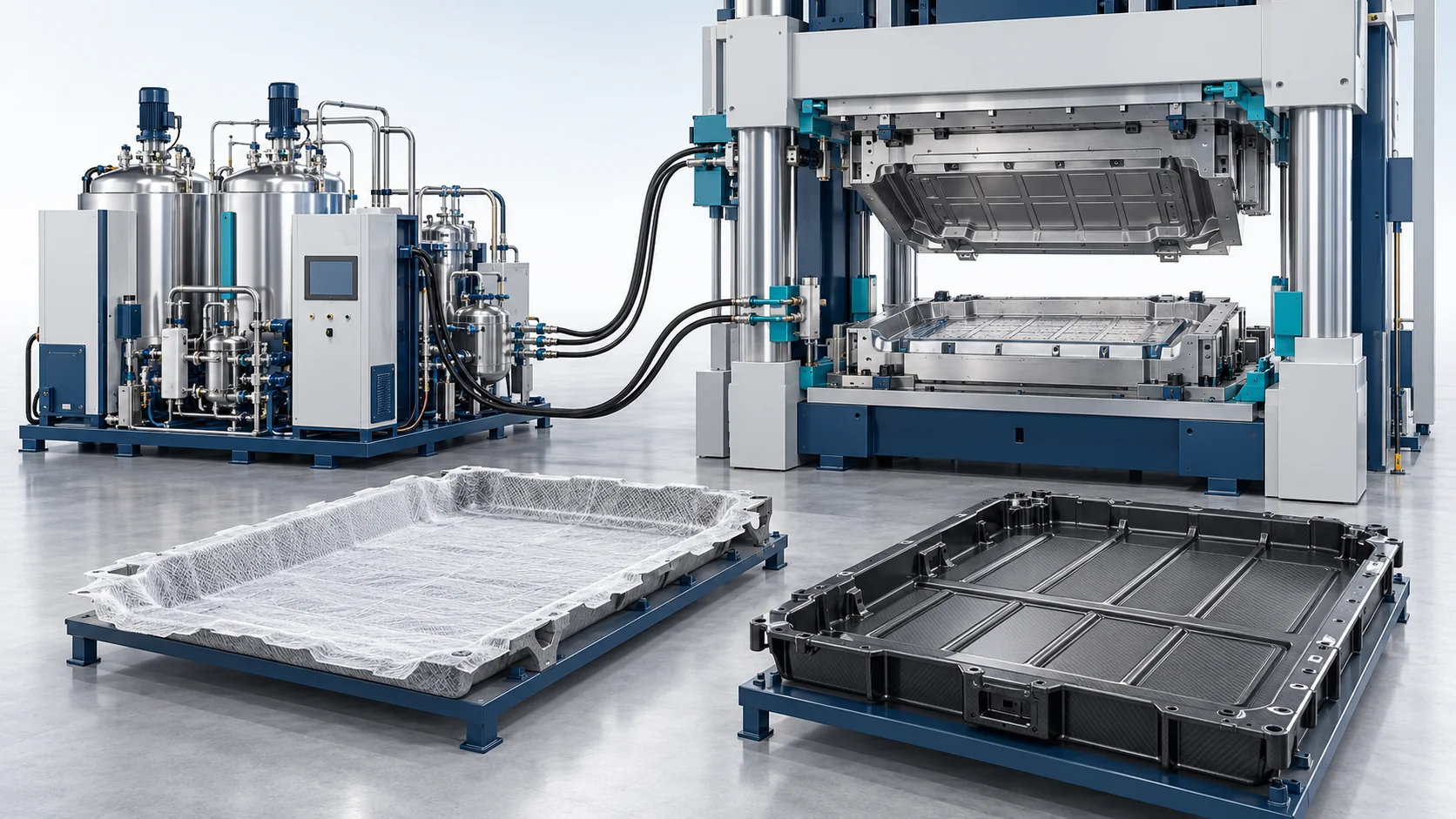
HP-RTM Machine | EV Battery Trays
High Pressure Polyurethane Machine


