
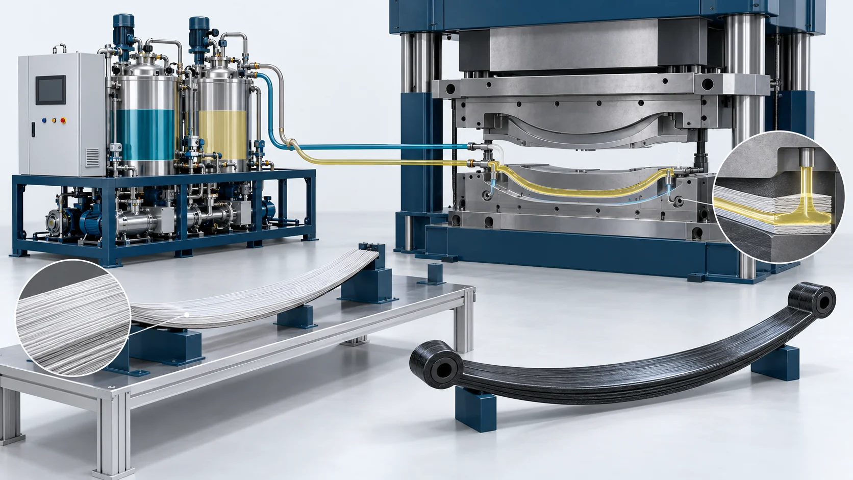
HP-RTM Machine | Composite Leaf Springs
HP-RTM resin metering and injection equipment for composite suspension leaf springs, configured for thick unidirectional glass-fiber preforms, mold vacuum and multi-zone thermal control.
Metering Output
20–60 kg/min configuration range
Reinforcement
Unidirectional glass-fiber preforms
Thermal Control
Thick-section exotherm management
Reference Cycle
240–360 s; complete molding process
Product Overview
Controlled impregnation and cure management for thick composite suspension laminates.
The HF-RTM-HP150-LS application configuration is an HP-RTM metering and injection system for glass-fiber composite leaf springs. It keeps reactive resin components separate during storage and conditioning, meters them at the selected ratio, and mixes them immediately before injection into a sealed mold containing the dry preform.
Spring performance depends on fiber direction, laminate consolidation and the quality of resin impregnation through the center clamping region. The equipment configuration coordinates resin flow, tool evacuation and press interlocks, while the mold and thermal circuits are designed around the spring thickness and camber. Increasing pressure alone cannot compensate for a poorly designed flow path or an excessively short resin processing window.
The supply can include the metering skid, self-cleaning impingement mixing head, vacuum unit, mold temperature control and PLC integration. Presses, matched tooling and automated preform loading are configured to the project scope. The material supplier defines the resin processing window; the component program defines load-deflection, fatigue and dimensional acceptance.
Explore the complete application solution · View the corresponding project case
Concept illustration — not a photograph of delivered equipment or a customer installation.
HP-RTM Application Workflow
Condition Resin Components
Condition and degas the separate resin and hardener or isocyanate streams according to the selected epoxy or polyurethane system. Confirm viscosity and usable processing time before setting the injection recipe.
Load and Locate the Spring Preform
Place the unidirectional glass-fiber stack in the matched mold with controlled orientation and thickness. Locate the thick center region and protect the preform from movement during filling.
Close, Seal and Evacuate the Mold
Confirm press position, clamp readiness and seal integrity. Evacuate the tool through the configured vacuum circuit; the supplied application reference is below 10 mbar absolute before injection.
Meter, Mix and Impregnate
Meter the two reactive components, mix at the impingement head and inject using a staged flow and pressure profile matched to the laminate permeability. Monitor the injection circuit and mold cavity independently.
Control Cure and Demold
Use separate mold thermal zones to manage the thick-section reaction exotherm and develop demolding strength. The reference complete molding window is 240–360 seconds and varies with resin and spring geometry.
Inspect and Validate the Spring
Trim the part and inspect fiber placement, dimensions and internal impregnation. Validate spring load-deflection and fatigue behavior using the component program acceptance plan.
Technical Specifications
Application engineering reference for the proposed configuration. Final equipment ratings and acceptance conditions are defined for the selected resin, preform, tool and press. Mixing pressure, injection-circuit pressure and mold-cavity pressure are specified separately. The reference cycle is a complete molding window, not injection time alone.
| Technical Parameter | HF-RTM-HP150-LS |
|---|---|
| Components | 2 reactive components; separate additive dosing optional |
| Output Range (g/s) | 20–60 kg/min; application configuration range |
| Mixing Ratio Range | Selected from resin supplier formulation; configured during application engineering |
| Ratio Accuracy | ±0.5% application acceptance target; operating point and method defined in the offer |
| Working Pressure | Selected for preform permeability and tool rating; injection-circuit and cavity limits specified separately |
| Target Components | Longitudinal and transverse composite suspension leaf springs |
| Reinforcement | Unidirectional glass-fiber preforms |
| Compatible Resin Systems | Fast-curing epoxy or polyurethane; wetted parts and recipe matched to formulation |
| Thickness Design Reference | 40–60 mm center region in supplied application brief; feasibility depends on laminate and resin |
| Mold Vacuum Reference | <10 mbar absolute before injection; tool seal and evacuation configuration dependent |
| Thermal Configuration | Separate mold heating/cooling zones for thick-section cure and exotherm control |
| Reference Complete Molding Window | 240–360 s; not injection time alone |
| Control System | PLC recipe storage, flow/ratio monitoring and press interlocks |
| Mixing Head | High-pressure impingement with mechanical self-cleaning; resin-specific configuration |
Built Around the Application Process
Controlled impregnation and cure management for thick composite suspension laminates.
Thick-Section Filling Strategy
Flow ramps, vacuum timing and gate placement are developed around the densely stacked glass preform and the thick center clamping region.
Exotherm-Aware Thermal Control
Multiple tool heating and cooling circuits manage temperature gradients in thick laminates and support repeatable cure profiles.
Closed-Loop Component Dosing
Recipe-controlled component flow and ratio monitoring provide a recorded basis for shot repeatability across different suspension spring designs.
Press and Vacuum Interlocks
PLC sequencing coordinates clamp readiness, tool evacuation, injection permission and pressure release for the selected press interface.
Spring-Specific Quality Planning
The workcell specification addresses fiber orientation, resin-rich zones, internal defects, camber and the load-deflection response required by the spring program.
Compare Application Configurations
Compare resin injection configurations for suspension leaf springs, EV battery trays and carbon-fiber body structures.
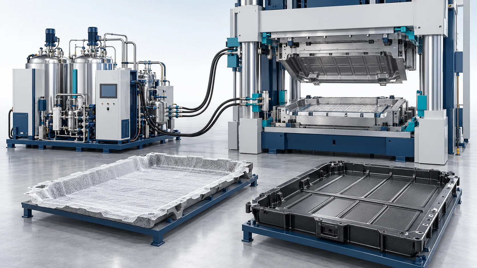
HP-RTM Machine | EV Battery Trays
High Pressure Polyurethane Machine
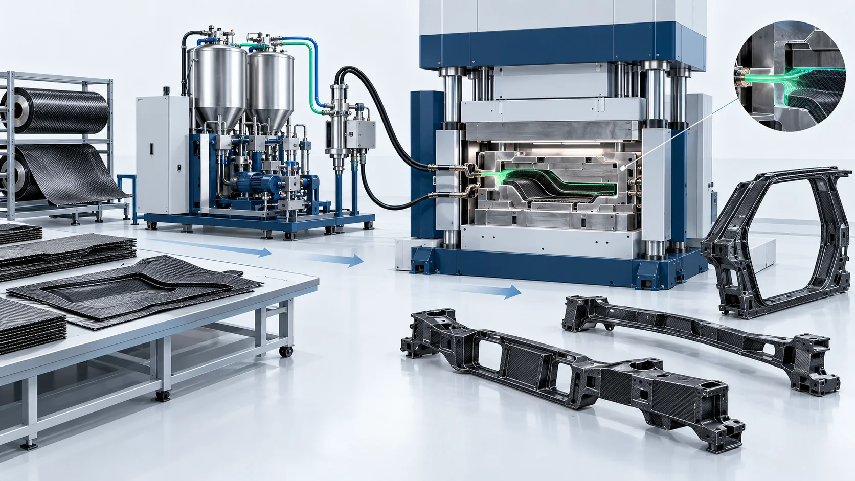
HP-RTM Machine | Carbon Fiber Body-in-White
High Pressure Polyurethane Machine


