
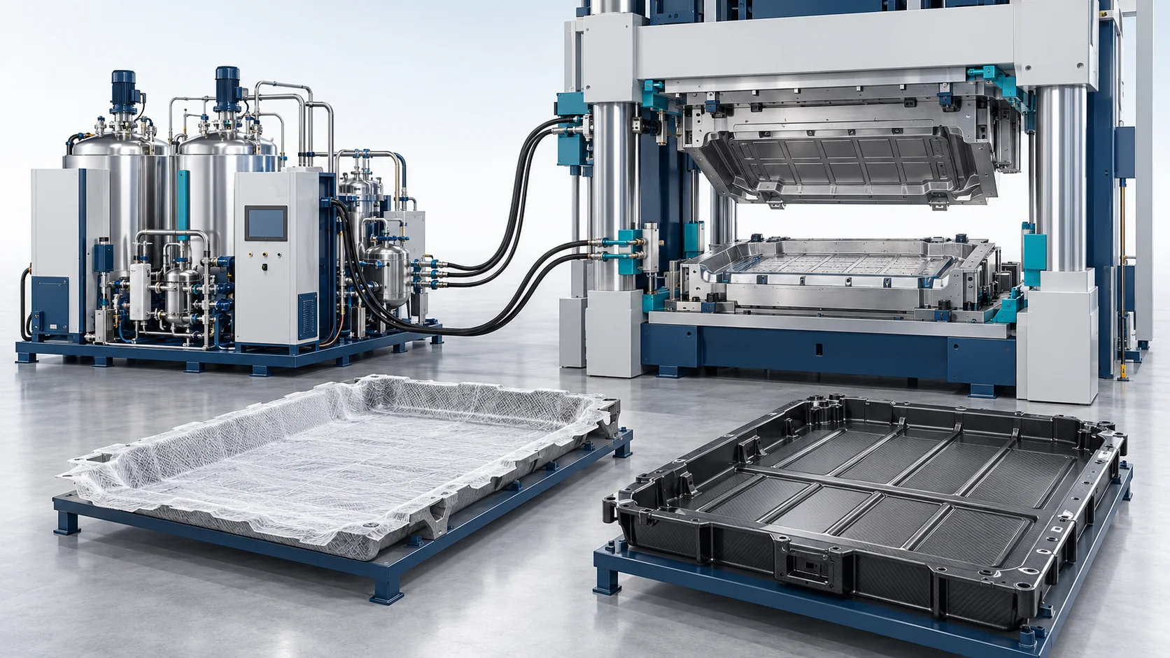
HP-RTM Machine | EV Battery Trays
HP-RTM resin injection equipment for composite EV battery lower trays and enclosures, combining higher-output metering, coordinated gate control, vacuum tooling and large-mold thermal management.
Metering Output
40–120 kg/min configuration range
Injection Layout
Tool-specific coordinated gates
Mold Envelope
Up to 2.5 × 1.8 m design reference
Reference Cycle
210–270 s; complete molding process
Product Overview
A large-part configuration focused on flow-front balance, molded interfaces and enclosure consistency.
The HF-RTM-HP150-BT application configuration meters and mixes reactive resin for continuous-fiber composite EV battery trays and lower enclosures. Its equipment scope combines a high-output metering skid, injection head or coordinated heads, tool vacuum, temperature control and a press control interface.
A battery tray presents long flow paths, local ribs, mounting features, inserts and a sealing flange. Shot sizing and gate timing are selected from the actual resin volume, preform permeability and fill-time window. The press, mold seals and venting arrangement must support the agreed injection strategy across the whole part.
Glass- or carbon-fiber reinforcement can be considered with a compatible fast-curing epoxy or polyurethane system. Flame retardancy, electrical properties, impact behavior and leak tightness are material and finished-part requirements. A UL94 rating describes a tested material specimen; battery thermal propagation performance requires its own pack or enclosure test plan.
The workcell can be supplied as the resin injection subsystem for an existing press, or expanded to include tooling, press coordination and handling. A large mold design envelope is a project input, rather than the footprint of the resin metering unit. Flange flatness, insert location, dimensional inspection and sealing checks are defined during application engineering.
Explore the complete application solution · View the corresponding project case
Concept illustration — not a photograph of delivered equipment or a customer installation.
HP-RTM Application Workflow
Define Tray Geometry and Resin Shot
Use the enclosure CAD, laminate schedule and resin data to establish shot mass, flow length, gate locations, insert positions and the available processing window.
Condition Materials and Load Inserts
Condition the separate resin components. Load the dry reinforcement and inserts into the prepared mold, keeping sealing surfaces and positioning features clear.
Seal and Evacuate the Large Mold
Verify press readiness, perimeter sealing and the vacuum circuit before permitting injection. Vacuum valve placement is designed to evacuate remote ribs and wide-area regions.
Coordinate Metering and Injection
Meter and mix the components, then sequence the chosen injection ports to balance flow fronts. Apply tool-specific pressure limits and record shot flow, ratio and cavity feedback.
Cure with Zoned Temperature Control
Coordinate mold heating/cooling and press holding until the resin develops the required demolding strength. The supplied reference complete molding window is 210–270 seconds.
Demold and Inspect Enclosure Interfaces
Trim and machine the specified interfaces, inspect flange geometry and insert placement, and run the agreed leak, mechanical, electrical and fire-related component tests.
Technical Specifications
Application engineering reference for the proposed configuration. Final equipment ratings and acceptance conditions are defined for the selected resin, preform, tool and press. Mixing pressure, injection-circuit pressure and mold-cavity pressure are specified separately. The reference cycle is a complete molding window, not injection time alone.
| Technical Parameter | HF-RTM-HP150-BT |
|---|---|
| Components | 2 reactive components; separate additive dosing optional |
| Output Range (g/s) | 40–120 kg/min; application configuration range |
| Mixing Ratio Range | Selected from resin supplier formulation; configured during application engineering |
| Ratio Accuracy | ±0.5% application acceptance target; operating point and method defined in the offer |
| Working Pressure | 40–150 bar reference injection-system range; mold-cavity limit specified separately |
| Target Components | EV battery lower trays, structural enclosures and under-shield modules |
| Compatible Resin Systems | Flame-retardant epoxy or polyurethane; viscosity and filler compatibility evaluated |
| Reinforcement | Continuous glass or carbon fiber; electrical properties depend on laminate construction |
| Tool Design Envelope | Up to 2.5 × 1.8 m in supplied application brief; press/tool configuration dependent |
| Injection Port Strategy | Single or coordinated multiple gates selected from mold flow and preform layout |
| Mold Vacuum Reference | <10 mbar absolute before injection; qualified with the actual sealed tool |
| Thermal Configuration | Multi-zone tool temperature control around surface, rib and mounting regions |
| Reference Complete Molding Window | 210–270 s; not injection time alone |
| Control System | PLC recipe and shot recording with vacuum, temperature and press interfaces |
| Mixing Head | High-pressure impingement and mechanical self-cleaning; material-specific selection |
Built Around the Application Process
A large-part configuration focused on flow-front balance, molded interfaces and enclosure consistency.
High-Output Resin Delivery
The 40–120 kg/min application range supports sizing for larger resin shots. Actual output is selected to fit the resin viscosity and usable fill-time window.
Coordinated Injection Ports
Tool-specific gate sequencing reduces unbalanced flow fronts around long paths, ribs and inserts; the number of heads and ports follows the mold design.
Large-Mold Vacuum and Sealing
Vacuum distribution and perimeter seal verification are integrated into the injection permission sequence for wide-area enclosure tools.
Zoned Tray Thermal Management
Separate thermal circuits address the cure response of large surfaces, thicker ribs and mounting regions while supporting dimensional control.
Defined Enclosure Acceptance
The project plan distinguishes metering-unit acceptance from flange flatness, leakage, impact, insulation and battery safety qualification of the finished enclosure.
Compare Application Configurations
Compare resin injection configurations for suspension leaf springs, EV battery trays and carbon-fiber body structures.
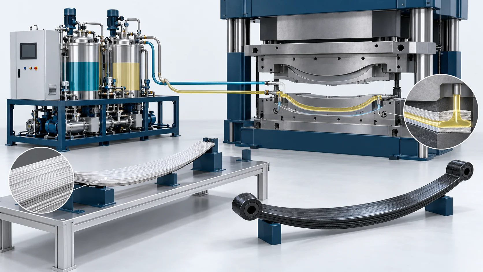
HP-RTM Machine | Composite Leaf Springs
High Pressure Polyurethane Machine
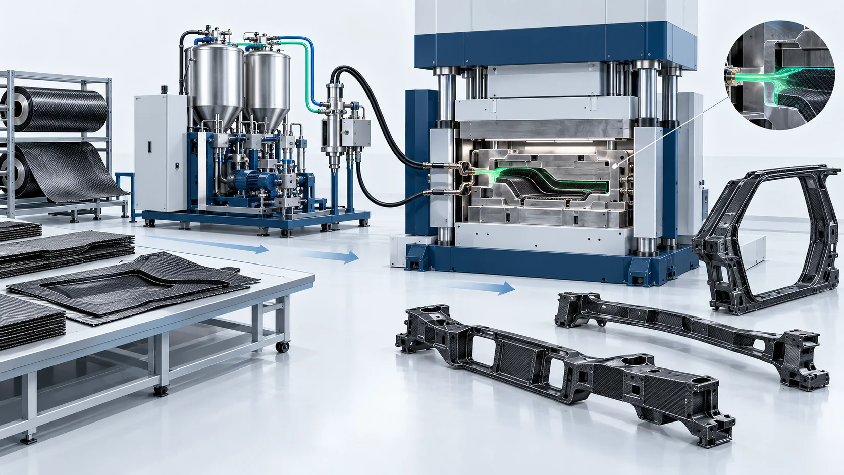
HP-RTM Machine | Carbon Fiber Body-in-White
High Pressure Polyurethane Machine


