

A VIP and PU hybrid cabinet usually fails at the fixture first, not at the formulation. The vacuum insulation panel is a pressure-sensitive part with a sealed barrier film, and the foam around it pushes outward in every direction while it rises. A fixture that only locates the cabinet halves and closes the press does half the job. The useful fixture decides where the foam pressure goes, how fast it arrives, and which surfaces never come into contact with the film.
That distinction matters most in refrigeration and cold-chain cabinet work, where the panel is thin, the foam gap around it is narrow, and the tolerance for a displaced or punctured panel is close to zero. The notes below cover what a hybrid cabinet foaming fixture must do, how to check it on a trial, and which items to settle before you order one.
Why a VIP panel changes the fixture job
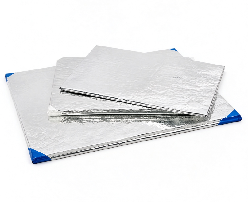
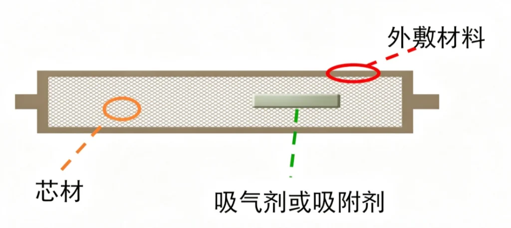
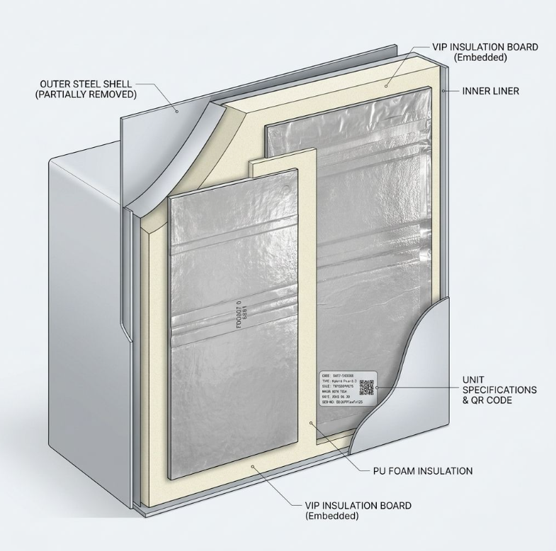
A vacuum insulation panel is a porous core held under vacuum inside a gas-tight barrier film. The film is the insulation. A crease, a puncture, or a seal that fails during handling lets gas back in, and the panel quietly drops to the performance of its core material. Nothing on the outside of the cabinet usually shows that this has happened until a thermal test or a complaint does.
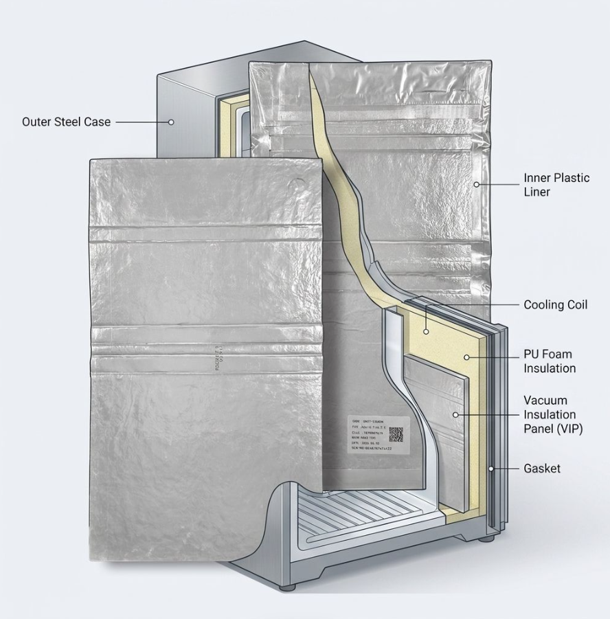
Rigid PU foam is forgiving by comparison. It expands against whatever confines it and takes the shape of the cavity. That difference drives the fixture design. In an all-foam cabinet the fixture is a dimensional tool: it holds the shell, controls foam distribution, and releases the part. In a hybrid cabinet the fixture is also a pressure-management device, because the reacting foam loads the panel from one or both faces through the whole rise.
Two design routes exist, and they do not share fixture requirements. In the insert route the panel sits in the cavity between the inner liner and the outer shell and is foamed in place. In the post-fit route the cavity is foamed first and the panel is applied to a finished surface. The insert route is where fixture design carries the risk, and it is the route this article addresses.
A second condition is worth settling early. Some cabinets use the panel only across a flat back or side wall, where the foam can be directed along the panel face. Others wrap the panel around a corner or place it in a narrow ribbed section. Corners concentrate foam pressure and are the first place a barrier film gets damaged, so a fixture proven on a flat panel is not automatically suitable for a wrapped one.
| Fixture function | What fails without it | What it protects |
|---|---|---|
| Panel location from a cabinet datum | Panel drifts during fill and the insulation band shifts | Thermal performance of the wall |
| Compliant face contact | Point loads crease or puncture the film | Vacuum integrity of the panel |
| Controlled clamp stops | Panel takes clamp load instead of the seal line | Panel thickness and flatness |
| Directed fill path | Foam front hits the panel face at full velocity | Film surface and foam bond |
| Venting at the panel edge | Trapped air displaces the panel rearward | Panel position and foam density |
Contact zones, datums and the surfaces that must stay clear
The panel should be located by a pocket or a ledge, not by clamping force. Clamping a panel into position works until the core compresses; after that the panel is thinner in the middle than at the edges, and the foam gap becomes uneven.
Locate from the cabinet. Use the outer shell or the liner as the datum, because panel thickness tolerance is typically wider than sheet metal tolerance, and a fixture built around the panel will not repeat from one panel lot to the next. The panel then sits in a pocket sized to its worst-case thickness, with a compliant pad taking up the difference.
Where the fixture should touch the cabinet
Clamping force belongs on the cabinet seal line and on rigid structure behind the panel, not on the panel face. Mechanical stops are the reliable way to enforce this. Set the stops so the shell closes to a fixed dimension, then let clamp pressure rise against the stops. The panel sees position, not load.
If the design does require the fixture to press on a panel face, use a pad with enough compliance to spread load over the whole panel area. A hard plate with a small high spot can be worse than no plate at all.
Protecting the barrier film at edges and corners
Every metal edge that can reach the panel needs a radius or a soft facing. Silicone, felt and PTFE-faced pads are common choices; the right one depends on mold temperature and on how often the pad is replaced. What matters is that the pad is a wear item with a change interval, not a permanent feature nobody inspects.
Edge gaps are a separate decision. A large gap between panel edge and cavity wall gives foam a path behind the panel, and the pressure on the two faces then differs. A gap that is too tight risks pinching the film as the shell closes. The workable figure comes from the foam system’s flow behaviour and from the panel supplier’s edge tolerance, so measure it on the trial rather than assume it.
Managing foam pressure around a panel
Foam pressure is not a single number. It builds as the material rises, peaks near the end of rise, then falls as the mass gels and cools. A fixture that holds the panel through the peak is doing its job; a fixture that holds it by over-clamping the panel has moved the damage somewhere you cannot see.
Gate position and fill direction
Do not aim the gate directly at a panel face. Use a runner or a deflector so the foam enters the cavity along a wall and reaches the panel as a spreading front rather than a jet. Where geometry allows, place the gate so the front arrives at the panel last, after it has lost velocity and started to build viscosity.
Wall thickness decides how much this matters. In a narrow foam gap the same shot volume produces a higher pressure peak than in a thick one, because the flow path is more restricted.
Venting and trapped air
Air in the cavity has to leave before the foam can occupy the space. If it cannot, it compresses, pushes back on the panel, and leaves a low-density region where it finally escapes. Put vents at the highest points of the cavity and at the panel edges, and check them on the first shot rather than after a week of production.
Shot size and the pressure peak
Shot size should cover the cavity volume minus the panel volume, plus what stays in the runner. Overfilling raises the pressure peak for no gain in density; underfilling leaves a void exactly where the panel needs support, and that void becomes a hot spot in service.
Shot size sets how much of the cavity the foam can occupy before the pressure peak arrives. <How To Calculate Shot Weight In Polyurethane> covers the shot weight calculation for PU.
Rise time and fill speed
Rise time sets how quickly the reacting mass reaches the panel, and it interacts with the gap it has to fill. A fast system in a thin gap builds pressure before the foam has spread far from the gate, which loads one area of the panel while the far end is still empty. A slow system spreads more evenly but tests the fixture for longer, and on a multi-station carousel it eats into cycle time. Neither is better in isolation. The workable combination comes from matching the reaction profile to the shot size, the gate position and the vent layout, then confirming it on a sectioned part rather than on a machine display.
Foam pressure and fill time are linked through the reaction profile, not only through machine output. <The Role Of Rise Time In Polyurethane Foaming> covers how rise time behaves in PU foaming.
Clamp force and metering accuracy together
Clamp force has to hold the shell against peak pressure and no more than the stops allow. On the machine side, ratio deviation changes both density and pressure. A cabinet foaming machine in our range holds dosing accuracy within plus or minus 0.3 percent across the working range, with material temperature controlled between 20 and 45 degrees Celsius, and that stability is what keeps a shot reproducible from part to part. Where ratio drifts, the fixture gets blamed for a pressure change it did not cause.
| Parameter | Effect at the panel | What to check |
|---|---|---|
| Gate position | Jet impact versus spreading front | Foam pattern on a sectioned part |
| Vent placement | Trapped air displacing the panel | Panel position after demold |
| Shot size | Pressure peak and void risk | Weighed shots against cavity volume |
| Rise profile | How fast pressure reaches the panel | Reaction profile at mold temperature |
| Clamp stops | Panel load versus seal line load | Stop contact marks on the shell |
| Metering ratio | Foam density and pressure level | Ratio records per shift |
Temperature and panel conditioning before the pour
The panel side of the fixture behaves as a heat sink. A heavy steel plate at room temperature pulls heat out of the foam touching it, the front slows there, and the result is a low-density skin against the panel instead of a bonded one. Tempering the contact surfaces, or insulating the fixture where it faces the panel, is usually cheaper than chasing the symptom through formulation.
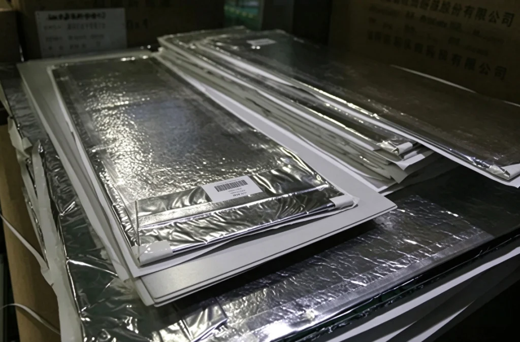
Panel conditioning matters for the same reason. A panel stored cold and moved into a warm, humid foaming area collects condensation on the film. Moisture on the barrier film interferes with adhesion, and at the edge seal it is the last thing you want. Bring panels to shop temperature in their packaging, open them at the line, and keep the open time short.
Mold temperature also drives demold. Pulling a cabinet while the foam is still soft loads the panel through the shell, and a panel that has been pushed at demold can look perfect and still sit out of position. Set demold from the part, not from the clock.
What to put in the fixture RFQ
Most fixture disputes trace back to a drawing that described the cabinet but not the panel. The RFQ should carry both, plus the tolerances that decide whether the fixture can be built at all.
| RFQ field | What to supply | Why it matters |
|---|---|---|
| Cabinet datums | Drawing with the surfaces the fixture may locate from | Stops the fixture being built around the panel |
| Panel envelope | Length, width, thickness, flatness and edge tolerance | Sizes the pocket and the compliant pad |
| Position tolerance | Allowed panel movement in three axes | Sets stop and vent design |
| Fill and vent plan | Intended gate and vent locations | Decides whether the fixture needs a runner |
| Contact surfaces | Which surfaces may be touched by pads | Protects the barrier film |
| Trial and acceptance | The checks that release the fixture | Prevents acceptance on one good part |
Two lines are worth removing from a draft RFQ before it goes out. Hold the panel firmly in place invites a clamp on the panel face; replace it with the datum, the pocket tolerance and the surfaces that must not be touched. A standard cabinet fixture with panel support is not a specification, because the panel changes the fill path, the venting and the clamp stops, and each of those has to be written down.
Trial protocol and acceptance checks
A fixture is accepted on evidence, not on a first part that looks right. Run the trial in this order and record each result.
- Locate and close dry. Close the fixture with a panel in place and no foam. Mark the panel position on the shell, open, and confirm the panel has not moved and shows no mark from a pad or a metal edge.
- Pour one shot at production settings. Record shot weight, ratio, material temperatures, mold temperature, clamp pressure and rise time from the same cycle.
- Measure panel position before demold. Use the fixture’s own reference or a gauge on the shell. Movement here points to fill path or venting, not to the panel.
- Section one part. Cut through the foam at three positions, including one at the panel edge, and inspect density and voids against the panel face. A bonded face with even cell structure is the result you want; a glassy skin or a void means temperature or fill path needs work.
- Check the cabinet after demold and again after cooling. Warpage that appears only after cooling is a foam relaxation question more than a fixture question.
Cabinet warpage after demold is often read as a mold problem while the foam is still relaxing. <Causes Of Shrinkage In Polyurethane Foam How To Control It> covers the causes of shrinkage in PU foam and the controls used against it.
A trial result covers the panel lot, the foam formulation and the settings used that day. Change the panel supplier, the foam system or the shot size and the evidence no longer applies; repeat the section check before running the line at rate.
FAQ
Can an existing cabinet foaming fixture be converted for VIP panels?
Sometimes, and the decision rests on three points. If the existing fixture locates from the cabinet and has mechanical stops, the conversion is mostly pads, a panel pocket and a revised fill and vent plan. If it clamps through the cavity or has no stops, the clamp circuit usually needs rebuilding, because there is no way to guarantee the panel never takes load. Add a sectioned trial before committing the line.
Does the panel need to be clamped, or can it sit loose in the cavity?
Position it, do not clamp it. The panel needs to be held in a pocket or against a ledge with a compliant pad so it cannot drift during fill, while clamp force goes to the shell and the stops. A loose panel migrates with the foam front; a clamped panel is compressed at the high spots and will not sit flat afterwards.
How do I tell whether the foam has pushed the panel out of position?
Measure before and after, not after alone. Mark or gauge the panel position in the closed fixture, then repeat the measurement on the demolded part or on a sectioned sample. A consistent shift in one direction points to gate placement or a blocked vent; random scatter points to panel handling before the pour.
What changes if the panel is fitted after foaming?
The fixture reverts to a dimensional tool and the panel becomes an assembly step. The pressure question moves to the adhesive and to the flatness of the foamed surface, and the fixture requirement becomes access and repeatable location for panel placement. That route is usually easier on fixtures and harder on panel protection during handling and bonding.
Specifying a hybrid cabinet foaming cell
Send the cabinet drawing with datum callouts, the panel drawing with thickness, flatness and edge tolerance, the allowed panel position tolerance in three axes, the foam system and target shot weight, the gate and vent locations you intend to use, and the station count and cycle time you are planning. That set is enough to size the fixture and the metering side together, without treating one clamp pressure figure as the whole specification.
Email Info@chinahaifeng.com or WhatsApp +86 13566296633 to review the layout with our engineers.
If you’re interested, check out these related articles:
RRIM Vs RIM Which Process Suits Your Structural Part
Measuring Polyurethane Foam Resilience A Practical Test Guide
Shore A Vs Shore D Hardness In Polyurethane
Causes Of Shrinkage In Polyurethane Foam How To Control It