Most polyurethane equipment problems are not pump failures. They are mixing failures that show up later as soft spots, streak lines, density drift, uncured patches, or shot-to-shot hardness variation. The mixing head is where those problems are either prevented or locked in. This guide explains the main head types by mixing principle, what each does well, and where each becomes the wrong choice.
What a Polyurethane Mixing Head Actually Does
A polyurethane mixing head has three jobs: bring the A and B streams together at the correct local ratio, create enough shear to erase concentration gradients, and deliver the mixture into the mold or onto the substrate before viscosity rise destroys flow. Because the reaction starts as soon as isocyanate meets polyol, the head must finish its work in seconds or fractions of a second.
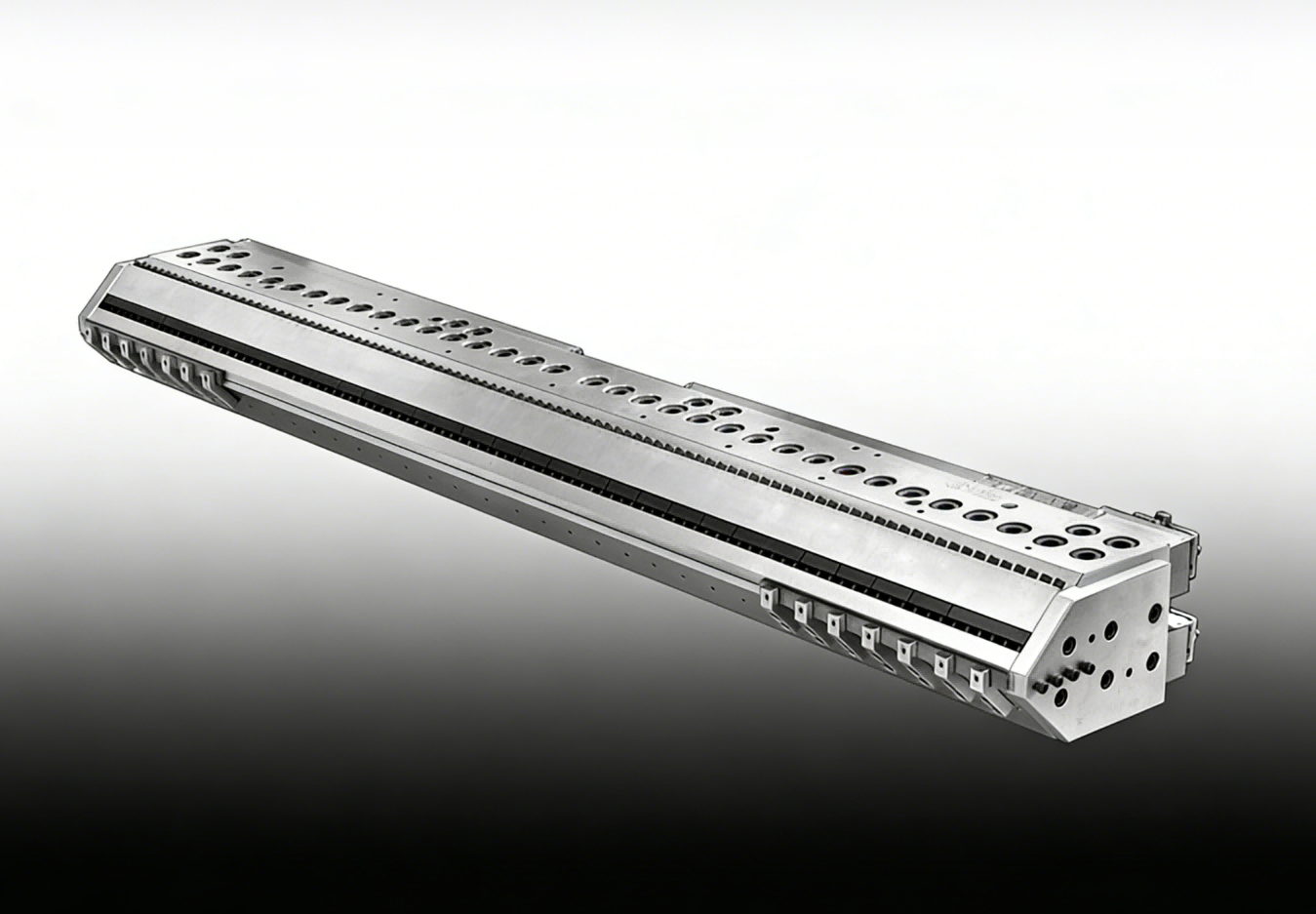
That timing explains why head selection is not primarily a brand decision. It is a residence-time, shear, and cleaning decision. The table below groups the main head types by mixing mechanism.
| Mixing head type | Mixing mechanism | Strongest fit | Main limitation |
|---|---|---|---|
| Low-pressure mechanical | Motor-driven stirrer in a small chamber | Elastomer casting, small to medium shots, filled systems, frequent color changes | Needs solvent or air purge after each shot; limited continuous output |
| High-pressure impingement | Opposed high-velocity streams collide in a small chamber | Fast-gelling foams, molded foam, RIM/RRIM, continuous panel lines | Needs high flow and pressure; sensitive to viscosity mismatch and lead-lag |
| Dynamic pin mixer | Rotating pins add mechanical shear inside the chamber | Highly filled or abrasive systems, high-viscosity elastomer | Mechanical wear; extra heat can require chamber cooling |
| Static mixer | Fixed elements split and recombine flow; no moving parts | Low-viscosity continuous dosing, ancillary streams | Pressure drop; risk of gel buildup in fast systems |
This is a simplification of commercially available designs, but the underlying choices follow the same four mixing principles [1].
Low-Pressure Mechanical Mixing Heads
Low-pressure heads drive a stirrer or rotor inside a small mixing chamber. They typically operate from roughly 2,000 to 6,000 rpm [1], depending on chamber volume, viscosity, and filler content. Because the chamber retains mixed material after the pour, the head needs a solvent or air purge after each shot. That makes these heads a practical fit for intermittent casting, especially solid and microcellular elastomers, where shot weights are moderate and hardness or color changes are frequent.
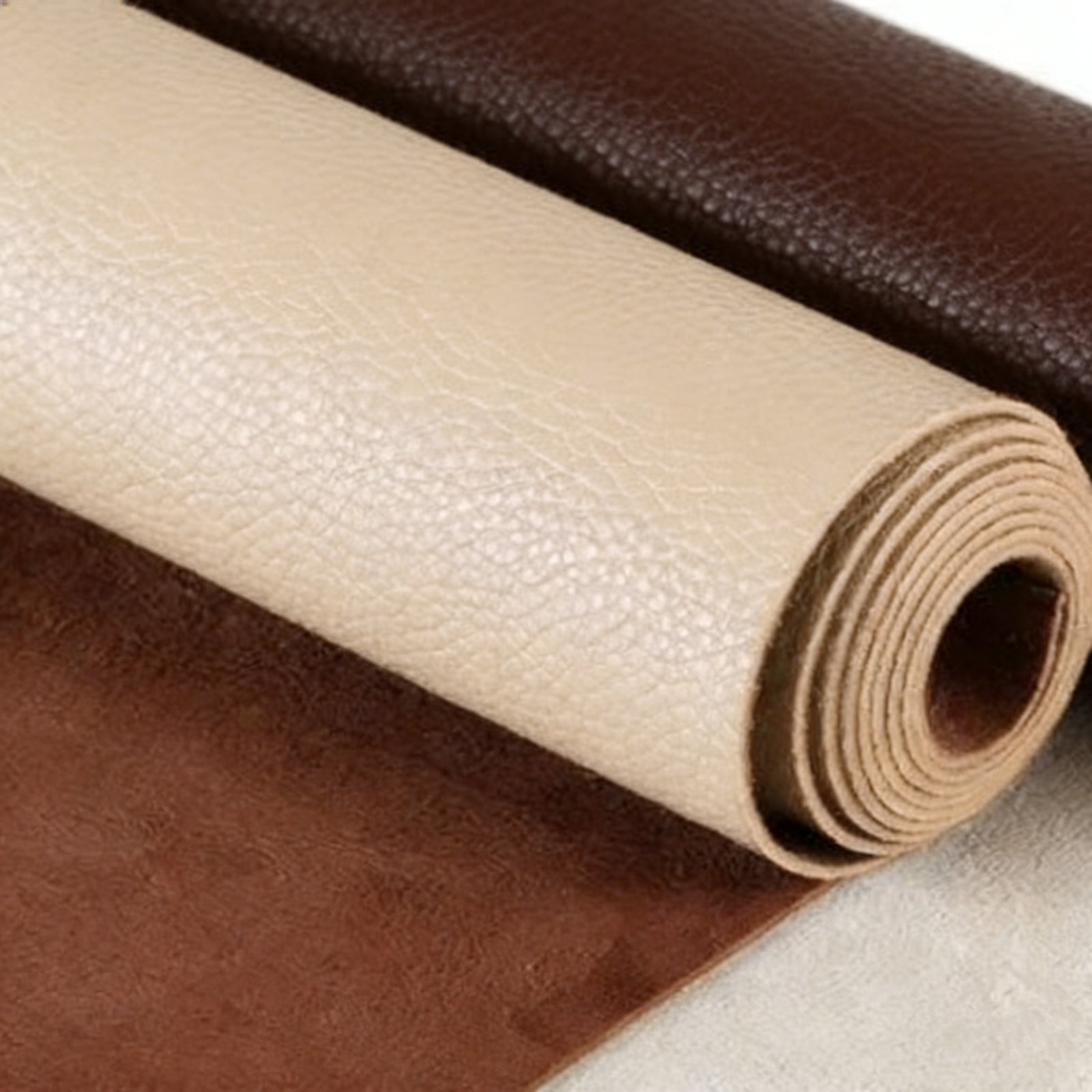
The same design logic carries into many elastomer-casting lines, where the head must handle MOCA or BDO curing agents without allowing air to become trapped in the mixture. In filled elastomer systems, gentle mechanical stirring can also preserve filler dispersion better than an impingement head that is running at the edge of its useful turndown.
Low-pressure mechanical heads are especially common in elastomer casting, where the same head may serve roller molds with MOCA or BDO curing agents. How Polyurethane Rollers Are Made From Casting To Cure covers how casting temperature, degassing, and head choice interact before the polymer reaches the mold.
High-Pressure Impingement Mixing Heads
High-pressure heads bring the A and B streams through opposed nozzles into a small chamber at pressures typically around 100 to 200 bar [1]. The streams collide, and the resulting turbulence does the mixing instead of a motor. A cleaning piston then scrapes the chamber, which is why these heads can cycle rapidly without solvent flushing. This principle is the core of most continuous slabstock, molded foam, and RIM lines.
Mixing quality in this design is a balance among nozzle Reynolds number, impingement angle, and chamber residence time. If one of those parameters moves outside the design window, streak lines or density variation appear before the formulation itself is at fault [2]. That means a high-pressure head cannot be treated as a universal mixing device; it has to be tuned to a flow window and a viscosity family.

High-pressure impingement is the same mixing principle used on most RIM and RRIM lines, including reinforced structural parts. RRIM Vs RIM Which Process Suits Your Structural Part covers when a structural part justifies the higher pressure and tooling demands of RRIM.
Dynamic Pin Mixers
Dynamic pin mixers are a smaller class, but they matter for filled or abrasive formulations. A row of rotating pins adds mechanical shear inside the chamber, which helps distribute fillers that impingement alone may leave agglomerated [3]. The trade-off is mechanical wear and higher heat input, so these heads need more maintenance attention and, on long runs, cooling of the mixing chamber.
Static Mixers
Static mixers contain fixed elements that repeatedly split and recombine the flow. They perform well with low-viscosity, slow-reacting streams in continuous dosing, such as inline additive blending or low-output coating setups. Their limitations are pressure drop and the risk of gel buildup, so they are rarely the main mixing device on a fast polyurethane foam line [4].

How to Match a Mixing Head to the Process
Start with output and shot window, not with machine type. Convert shot weight and mold fill time into a required flow:
Required flow (g/s) ≈ shot weight (g) ÷ pour time (s)
For example, a 360 g shot poured in 3 s requires about 120 g/s. Compare that number against the head’s verified stable turndown rather than its maximum rated output. A head that mixes well only at full flow may create off-ratio fill at the start of a short shot.
Once a head principle is chosen, the confirming step is a shot-weight calculation, because nominal output is only useful when it is tied to actual mold fill time. How To Calculate Shot Weight In Polyurethane covers the worksheet approach for translating part volume and density into the shot size a head must deliver.
Beyond flow, four process variables change the decision:
- Viscosity and A/B ratio: wide viscosity differences demand more impingement energy or mechanical shear to reach uniform mixing.
- Filler content: abrasive fillers push the choice toward hardened chambers or dynamic pin designs.
- Cream time and gel time: fast systems require the shortest possible residence between mixing and mold entry.
- Cleaning method: solvent flushing, air purge, or self-cleaning pistons each fit different production schedules.
If you are actively sizing a head, the fastest way to narrow the choices is to send three data points — maximum shot weight, required cycle time, and A/B viscosity at process temperature — to Info@chinahaifeng.com. State whether the line will run open foam, integral skin, or solid elastomer, because cleaning and pressure requirements change with each process family.
Failure Modes That Start at the Head
Some of the most common process defects are head problems in disguise:
- Lead-lag error on high-pressure heads: one stream arrives before the other at the start of the shot, creating an off-ratio slug that becomes the first material into the mold.
- Worn nozzles: progressive wear changes the impingement pattern and produces gradual density drift rather than a sudden failure.
- Inadequate flushing on mechanical heads: cured residue accumulates in the chamber, then releases as particles in later shots.
- Cold recirculation return: if the head is not kept at the same temperature as the metering loop, the first shot can show different cream time and viscosity from later shots.
Each of these follows a cause-and-effect chain, so the fix usually belongs at the head rather than in the formulation.

Selection Checklist
- Define the actual shot size and pour-time window.
- Identify whether the process is continuous or intermittent.
- Record A and B viscosity at process temperature, not ambient.
- Note filler type and loading, if any.
- Confirm whether solvent flushing is acceptable or a self-cleaning head is required.
- Test the head inside its stable turndown range, not only at nominal output.
Specify the Right Head for Your Line
To get a head recommendation that matches the process instead of a catalog number, send the following to Info@chinahaifeng.com:
- Shot weight or continuous output
- A/B mixing ratio and viscosity at process temperature
- Cream time and gel time
- Filler type and loading
- Available cleaning method
The inquiry can be as short as five lines. Haifeng Polyurethane Machinery will confirm the metering and head configuration from the process data, so the discussion stays on mixing quality rather than brochure numbers.
Frequently Asked Questions
What is the difference between low-pressure and high-pressure mixing heads?
Low-pressure heads use a motor-driven stirrer and require flushing after the shot. High-pressure heads mix by stream collision and use a cleaning piston, which allows faster cycling without solvent flushing.
Can one mixing head handle multiple polyurethane formulations?
A head can handle multiple formulations when they fall inside the same flow, viscosity, and reactivity window. Wide formulation changes usually require a different nozzle set, pressure setting, or head size.
How do I know if a mixing head is undersized?
An undersized head often shows correct ratio at nominal output but off-ratio fill at short shots, plus density variation or streak lines at the highest required flow.
Why is lead-lag adjustment important on high-pressure heads?
If one component stream enters the chamber before the other, the first part of the shot is off-ratio. Lead-lag adjustment synchronizes the two streams so the entire shot enters the mold with the intended chemistry.
Do static mixers work for polyurethane foaming?
They can work in low-viscosity, slow-reacting continuous processes, but they are not suitable for most fast foam lines because of pressure drop and gel-buildup risk.
References
[1] G. Oertel, Ed., Polyurethane Handbook, 2nd ed. Munich, Germany: Hanser Publishers, 1994.
[2] C. W. Macosko, RIM: Fundamentals of Reaction Injection Molding. Munich, Germany: Hanser Publishers, 1989.
[3] D. Randall and S. Lee, Eds., The Polyurethanes Book. New York, NY, USA: John Wiley & Sons, 2002.
[4] M. Szycher, Szycher’s Handbook of Polyurethanes, 2nd ed. Boca Raton, FL, USA: CRC Press, 2013.
If you’re interested, check out these related articles:
What Is Semi Rigid Polyurethane Foam
Measuring Polyurethane Foam Resilience A Practical Test Guide
Shore A Vs Shore D Hardness In Polyurethane