
Heavy Truck Panel RIM/LFI Solution
Robotic chopped-fiber deposition and PU delivery for configured LFI applications, with separately defined closed-mold RIM interfaces.
Agile, High-Impact Composite Manufacturing for Heavy Commercial Vehicles
Robotic chopped-fiber deposition and PU delivery for configured LFI applications, with separately defined closed-mold RIM interfaces.
Equipment and process scope
PU metering, chopper/mixing head, robot and controls; tooling, press, fiber supply and any distinct RIM configuration are separately specified.
Validation and production planning
Open-mold LFI and closed-mold RIM are distinct routes; one configuration does not automatically perform both. PU flow and fiber-chopper capacity constrain achievable fiber content together. The 45% fiber maximum is not assumed at simultaneous maximum PU flow. Impact, mass and tooling savings are part/project comparisons, not general machine guarantees. At the stated minimum PU flow of 100 g/s (360 kg/h) and maximum fiber feed of 60 kg/h, the continuous fiber mass fraction is at most 14.3%; reconcile the stated 15–45% fiber range and instantaneous versus sustained flow basis.
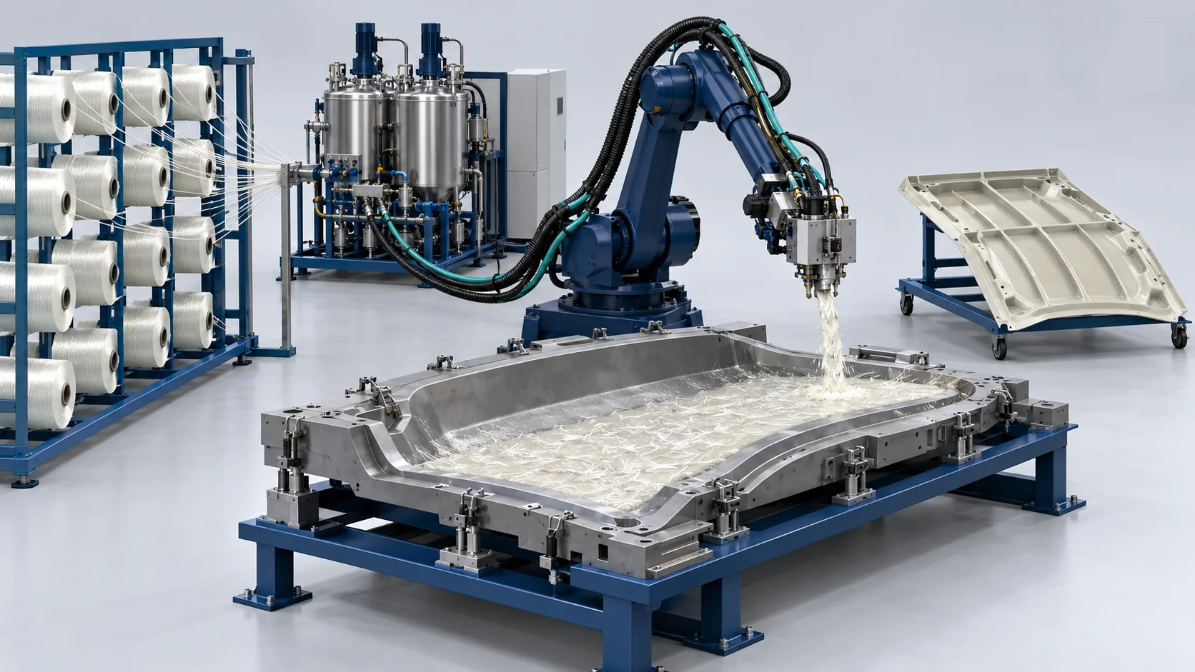
PU metering, chopper/mixing head, robot and controls; tooling, press, fiber supply and any distinct RIM configuration are separately specified. Open-mold LFI and closed-mold RIM are distinct routes; one configuration does not automatically perform both. PU flow and fiber-chopper capacity constrain achievable fiber content together. The 45% fiber maximum is not assumed at simultaneous maximum PU flow. Impact, mass and tooling savings are part/project comparisons, not general machine guarantees. At the stated minimum PU flow of 100 g/s (360 kg/h) and maximum fiber feed of 60 kg/h, the continuous fiber mass fraction is at most 14.3%; reconcile the stated 15–45% fiber range and instantaneous versus sustained flow basis.Generated concept illustration for process discussion; not a photograph of the specified machine, a customer facility or a delivered project.
Turnkey Commercial Vehicle LFI Manufacturing Workflow
Configuration sequence from the supplied brief. Material, tool, pressure/temperature basis and complete line balance require verification. Open-mold LFI and closed-mold RIM are distinct routes; one configuration does not automatically perform both. PU flow and fiber-chopper capacity constrain achievable fiber content together. The 45% fiber maximum is not assumed at simultaneous maximum PU flow. Impact, mass and tooling savings are part/project comparisons, not general machine guarantees. At the stated minimum PU flow of 100 g/s (360 kg/h) and maximum fiber feed of 60 kg/h, the continuous fiber mass fraction is at most 14.3%; reconcile the stated 15–45% fiber range and instantaneous versus sustained flow basis.
Automated In-Mold Coating (IMC) Application
Supplied process reference: A dedicated robot sprays a thin barrier coat of water-borne IMC across the heated cast aluminum mold (75°C) to yield Class-A finishes.
16 MPa High-Pressure Impingement Proportioning
Supplied process reference: Dual-cylinder metering pumps displace structural polyol and isocyanate at 16.0 MPa under continuous Coriolis mass flow measurement.
In-Air Fiber Chopping & Robotic Laydown
Supplied process reference: The robot sweeps the tool; 25 mm glass rovings are chopped at 45 kg/h and wetted in mid-air by polyurethane fans across the open mold.
Reference Solution Engineering Envelope
Supplied configuration and validation references; material/component results are separate from equipment ratings.
| Parameter | Value / Unit | Applicable Configuration / Conditions |
|---|---|---|
| Polyurethane Fluid Discharge Output | 100 to 500 g/s | Continuous variable high-pressure axial piston proportioner; supplied configuration or material target, pending the applicable original records |
| Continuous Glass Chopper Rate | 10 to 60 kg/hour | High-speed electric rotary chopper with tungsten blades; supplied configuration or material target, pending the applicable original records |
| Chopped Fiber Length Envelope | 12.5 to 50.0 mm | Programmed rotary knife drum with step adjustments; supplied configuration or material target, pending the applicable original records |
| Required Mold Clamping Force | 200 to 400 Tons (Low pressure) | Low-cost precision cast aluminum or forged steel tools; supplied configuration or material target, pending the applicable original records |
| Charpy Notched Impact Resistance | Greater than or equal to 45 kJ/m² | ISO 179 testing on 25 mm long-fiber composite core; supplied configuration or material target, pending the applicable original records |
| Tooling Capital Expense Savings | Up to 60% reduction vs SMC | Driven by lower in-mold pressure permitting aluminum tools; supplied configuration or material target, pending the applicable original records |
Core Equipment for This Solution
PU metering, chopper/mixing head, robot and controls; tooling, press, fiber supply and any distinct RIM configuration are separately specified.
Core Advantages of Haifeng LFI Systems
Configured equipment functions and interfaces for the selected material and tooling.
2x Impact Toughness vs SMC
Supplied configuration function: Entangled 50 mm long glass fibers absorb severe road impacts without brittle cracking. Project-dependent performance requires validation.
60% Tooling Budget Cut
Supplied configuration function: Low cavity pressures (< 3.0 MPa) allow the use of cast aluminum tooling, slashing initial model development costs. Project-dependent performance requires validation.
20% Body Component Lightening
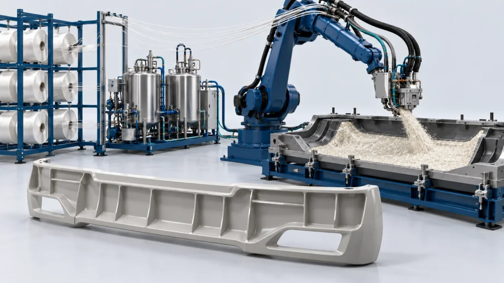
Supplied configuration function: Microcellular structural core lowers panel density, shedding up to 4.3 kg on single truck bumpers. Project-dependent performance requires validation.
Agile Robot-Driven Versatility
Supplied configuration function: 6-axis articulated robots adjust glass lengths and spray densities on the fly matching structural stress zones. Project-dependent performance requires validation.
Related Project Draft
An anonymous project brief from the supplied document. Original attribution, dates, acceptance and outcome records require verification before public use.
Frequently Asked Questions
How does LFI eliminate fiber preforming and sheet preparation steps?
Why does LFI require only a 300-ton press for 2.4-meter truck bumpers?
Can this solution produce variable thickness profiles on single parts?
How does in-mold coating (IMC) work with the LFI production cycle?
Discuss Your Production Goals
Share your product or drawing, material system, target output, automation needs and factory utilities so the equipment and interfaces can be configured.


