
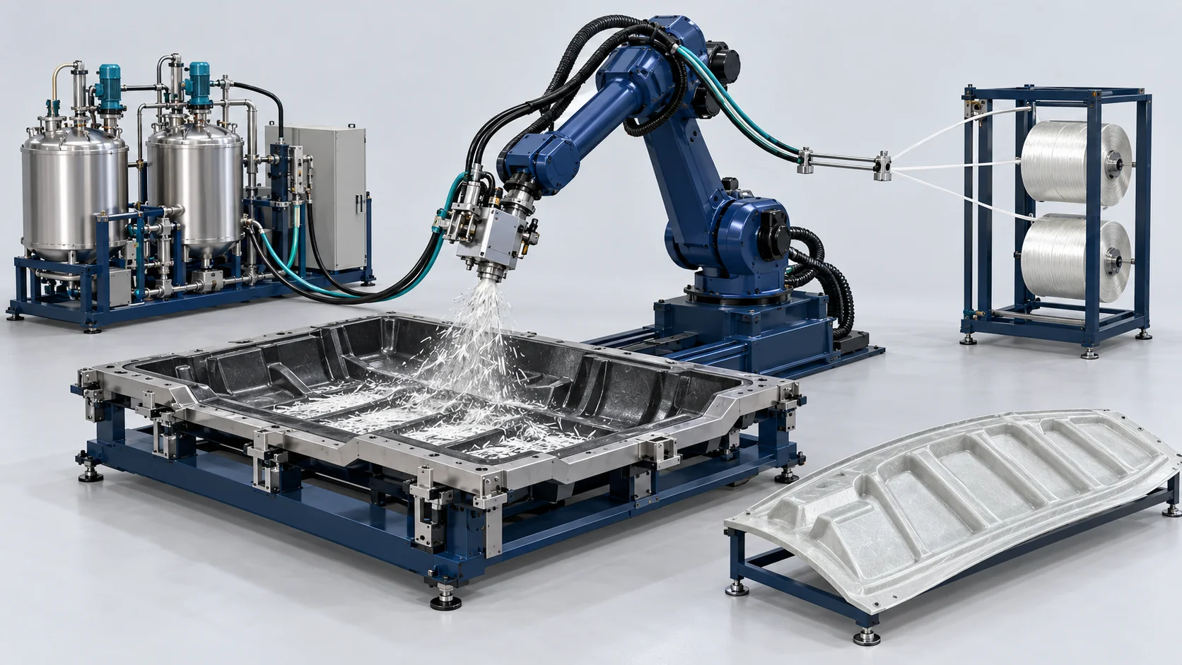
Robotic LFI System | Composite Body Panels
Robotic chopped-fiber deposition and PU delivery for configured LFI applications, with separately defined closed-mold RIM interfaces.
Robotic Long Fiber Injection for Heavy Truck Body Panels
Robotic chopped-fiber deposition and PU delivery for configured LFI applications, with separately defined closed-mold RIM interfaces.
Robotic chopped-fiber deposition and PU delivery for configured LFI applications, with separately defined closed-mold RIM interfaces.
PU metering, chopper/mixing head, robot and controls; tooling, press, fiber supply and any distinct RIM configuration are separately specified.
Open-mold LFI and closed-mold RIM are separately specified routes. PU delivery and glass-fiber chopping have independent equipment capacity ratings; their maximum values do not represent a simultaneous operating point and must not be divided to infer a working formulation. The 15–45% fiber-content selection is set by the chosen formulation. Its percentage measurement basis is defined in the agreed recipe and is not specified here. Part impact, mass and tooling comparisons are separate from machine ratings.
Concept illustration: Generated concept illustration for process discussion; not a photograph of the specified machine, a customer facility or a delivered project.
Material Flow and Working Principle
Continuous Glass Fiber Drawing & Roving Feeding
Continuous E-glass roving is drawn from external creels into the robot-mounted chopper motor, which cuts fibers to programmed lengths from 12.5 to 50 mm at rates up to 60 kg/h.
High-Pressure Impingement Chemical Metering
Axial piston metering pumps deliver structural polyol and modified isocyanates at 16.0 MPa into the mixing chamber under Coriolis mass flow regulation.
In-Air Wetting & Robotic Open-Mold Laydown
The six-axis robot sweeps over the open heated lower mold; chopped fibers and impinged polyurethane mix intersect in mid-air, depositing a uniform composite veil across the tool surface.
Low-Tonnage Hydraulic Mold Clamping
The hydraulic press closes the tool under 300 tons of force; low internal cavity pressures (2.0 MPa) allow the resin to expand and encapsulate fibers without core dry spots.
In-Mold Curing & Automated Part Extraction
The polyurethane cures isothermally at 75°C in 180 seconds; hydraulic ejectors loosen the finished heavy bumper, transferred by vacuum offloaders for automated deflashing.
Model and Technical Parameters
Supplied HF-LFI120-ROB configuration references. Open-mold LFI and closed-mold RIM are separately specified routes. PU delivery and glass-fiber chopping have independent equipment capacity ratings; their maximum values do not represent a simultaneous operating point and must not be divided to infer a working formulation. The 15–45% fiber-content selection is set by the chosen formulation. Its percentage measurement basis is defined in the agreed recipe and is not specified here. Part impact, mass and tooling comparisons are separate from machine ratings.
| Technical Parameter | HF-LFI120-ROB |
|---|---|
| Components | Polyurethane 2 Streams + Continuous Glass Roving |
| Output Range (g/s) | PU Output: 100 to 500 g/s; Glass Chopper: 10 to 60 kg/h; independently rated capacities, not simultaneous recipe working points |
| Mixing Ratio Range | PU Ratio 100:120 to 100:160; Fiber content 15% to 45%, selected by formulation; percentage basis defined by the agreed recipe, not inferred from equipment flow limits |
| Ratio Accuracy | ±0.3% (PU flow) / ±1.0% (Fiber-content reference; measurement basis defined in the agreed recipe) |
| Power Supply | 380V, 3-Phase, 50Hz (Custom 440V/480V 60Hz optional) |
| Working Pressure | 14.0 to 16.5 MPa (Polyurethane high-pressure lines) |
| Tank Capacity (L) | Day tanks: 2 x 250 L (Stainless steel with thermal jackets) |
| Weight | 6,500 kg (Robot, chopper head, and metering skid) |
| Dimensions (L×W×H) | 6500 mm x 4200 mm x 3200 mm (Robot operating cell) |
| Chopped Fiber Length Range | 12.5 to 50.0 mm (Electrically adjustable blade); Continuous E-glass roving; configuration-specific or part-test reference |
| Charpy Notched Impact Toughness | ≥ 45 kJ/m² (ISO 179 notched impact test); Cured polyurethane composite panel; configuration-specific or part-test reference |
| Required Tool Clamping Pressure | 2.0 to 3.5 MPa (Low-pressure aluminum tools); Press in-mold cavity pressure; configuration-specific or part-test reference |
| Tooling Cost Saving vs SMC | Up to 60% tooling expense reduction; Cast aluminum vs forged steel tools; configuration-specific or part-test reference |
Key Equipment Features
PU metering, chopper/mixing head, robot and controls; tooling, press, fiber supply and any distinct RIM configuration are separately specified.
2x Impact Toughness vs SMC
Supplied configuration reference: In-situ long fibers (up to 50 mm) absorb severe road impacts, preventing brittle shattering common to SMC. Actual capability requires material and tooling validation.
60% Lower Tooling Investment
Supplied configuration reference: Low in-mold pressure (< 3.0 MPa) permits low-cost cast aluminum tools, slashing initial tooling budgets. Actual capability requires material and tooling validation.
20% Component Weight Savings
Supplied configuration reference: Microcellular structural foam matrix cuts finished truck panel weight by 20% compared to solid sheet molding. Actual capability requires material and tooling validation.
6-Axis Robotic Path Precision
Supplied configuration reference: Articulated robots follow the selected deposition path. The stated ±1.5% fiber-distribution reference applies to the agreed recipe and measurement basis; material and tooling validation determine actual capability.


