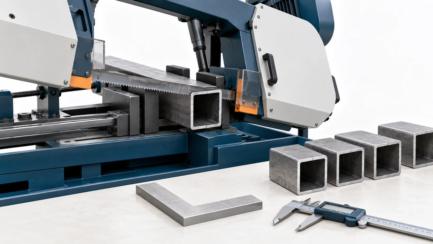
The weld-fit-up accuracy of Haifeng polyurethane equipment starts at the bandsaw blanking stage. Each 0.5°/100 mm deviation in cut-face perpendicularity can increase weld-fit-up gap unevenness by more than 0.3 mm and raise welding distortion by 20%–30%, ultimately putting the servo metering-pump mounting-base flatness out of tolerance during final assembly. If end-face perpendicularity of pipeline supports or flange blanks exceeds 0.2 mm/100 mm, flange sealing faces can skew after welding and reduce the tank airtightness-test pass rate (Haifeng requirement: no leakage at 0.02 MPa for 30 min).
Key process parameters at a glance:
| Parameter | Haifeng standard | Industry reference | Related accuracy indicator |
| Blank length tolerance (L <3000 mm) | ±1.0 mm | ±1.0 mm | Weld fit-up gap ≤0.5 mm |
| Blank length tolerance (L ≥3000 mm) | ±0.5 mm | ±0.5 mm | Consistent frame-tube lengths |
| Cut-face perpendicularity (height ≤200 mm) | ≤0.2 mm/100 mm | ≤0.5° | Weld-fit-up contact |
| Cut-face perpendicularity (height >200 mm) | ≤0.15 mm/100 mm | ≤0.3° | Tank-shell seam alignment after rolling |
| Sawn-surface roughness | Ra ≤12.5 μm | Ra ≤12.5 μm | Weld face free of oil residue |
| Burr height at cut end | ≤0.1 mm on weld-fit-up face | ≤0.5 mm | Control of weld porosity/lack of fusion |
| Saw-wheel radial runout | ≤0.15 mm | 0.12–0.20 mm | Sawn-face straightness ≤0.3 mm/m |
| Saw-wheel face runout | ≤0.15 mm | 0.12–0.20 mm | Sawn-face flatness |
| Blade-guide horizontal accuracy | ≤0.10 mm/100 mm | ≤0.15 mm/100 mm | Cut perpendicularity ≤0.2 mm/100 mm |
| Feed-system positioning accuracy | ≤±0.10 mm/500 mm | ≤±0.20 mm/500 mm | Batch-length consistency CV ≤0.3% |
| Feed-system repeat positioning | ≤±0.05 mm | ≤±0.10 mm | Stable batch blank dimensions |
| Blade tension (steel) | 20–25 N/mm² | 15–30 N/mm² | Blade deviation ≤0.1 mm/m |
| Cutting speed (Q235B/Q345B carbon steel) | 60–100 m/min | 50–120 m/min | Balance cut quality and output |
| Cutting speed (304/316L stainless) | 30–50 m/min | 30–60 m/min | Control work hardening and tool life |
| Cutting speed (6061/7075 aluminum) | 200–400 m/min | 200–500 m/min | Control burrs |
| Feed per tooth (carbon steel) | 0.04–0.08 mm/tooth | 0.04–0.16 mm/tooth | Balance chip shape and cutting force |
| Coolant concentration | 8%–12% emulsion | 5%–15% | Blade life ≥3000 cuts |
| Blanking ambient temperature | 10–40°C | — | Thermal expansion effect ≤0.01 mm/m |
1. Scope
1.1 Applicable operations
This SOP applies to bandsaw blanking of the following Haifeng polyurethane-equipment components:
| Part to cut | Typical material | Typical size | Related equipment indicator |
| Frame square tube/rectangular tube | Q235B/Q345B | 40×40–120×120 mm | Frame weld-fit-up gap ≤0.5 mm |
| Tank-shell plate blank | 304/316L | 3–8 mm thick | Tank-shell seam accuracy after rolling |
| Pipeline-support sections | Q235B/304 | Angle/channel/flat bar | Accurate pipeline fixing-point position |
| Round-bar flange blanks | 304/316L/45# | Φ50–Φ300 mm | Flange sealing-face flatness ≤0.02 mm |
| Pouring-platform frame sections | Q235B/Q345B | Square/rectangular tube | Pouring-path repeatability ±0.05 mm |
| Electrical-cabinet brackets | Q235B/cold-rolled sheet | Angle/flat bar | Alignment of cabinet mounting holes |
| Mixing-head mounting-base blanks | Alloy steel/45# | Φ80–Φ200 mm | Mixing-head alignment ≤0.03 mm |
2. Pre-Job Preparation and Machine Accuracy Verification
2.1 Check technical documents and material
| No. | Item | Accuracy requirement | Acceptance criterion |
| 1 | Blanking list | Material, size, quantity, and cut length specified | Matches BOM |
| 2 | Material certificate | Grade matches drawing | Chemical-composition and mechanical-property reports included |
| 3 | Visual material inspection | No bending, twisting, or rust | Bend ≤2 mm/m; twist ≤1°/m |
| 4 | Actual material dimensions | Section-size deviation ≤±0.5 mm | Measure with vernier caliper and record |
| 5 | Blanking process card | Saw parameters, clamping plan, and inspection requirements | Includes weld-shrinkage allowance |
2.2 Verify machine accuracy
Calibrate the bandsaw regularly under the machine calibration procedure; calibration error for critical parameters must be ≤0.05 mm. Perform accuracy inspection according to JB/T 15187.1-2025, “CNC Horizontal Bandsawing Machines—Part 1: Accuracy Inspection,” and JB/T 4318.1-2026, “Horizontal Bandsawing Machines—Part 1: Accuracy Inspection.”
| Calibration item | Haifeng standard | Interval | Inspection tool |
| Radial runout of drive/idler saw wheels | ≤0.15 mm | Quarterly | Dial indicator and magnetic base |
| Face runout of drive/idler saw wheels | ≤0.15 mm | Quarterly | Dial indicator |
| Worktable flatness | ≤0.10 mm/500 mm | Quarterly | Precision level/straightedge and feeler gauge |
| Blade-guide horizontal accuracy | ≤0.10 mm/100 mm | Monthly | Dial indicator and master test piece |
| Blade-position error from combined guide errors | ≤0.15 mm | Monthly | Indicator |
| Feed-system positioning accuracy | ≤±0.10 mm/500 mm | Monthly | Laser distance meter/master gauge block |
| Feed-system repeat positioning | ≤±0.05 mm | Monthly | Dial indicator and master test piece |
| Saw-frame travel parallelism to guideway | ≤0.10 mm/1000 mm | Every 6 months | Dial indicator and straightedge |
| Blade perpendicularity to worktable | ≤0.1 mm/100 mm | Monthly | Square and feeler gauge |
2.3 Verify blade and fixture accuracy
| Tool/component | Accuracy requirement | Interval | Inspection tool |
| Blade tooth pitch | Match workpiece section size | Each blade batch | Tooth-pitch gauge |
| Blade tooth set | Symmetric left/right; deviation ≤0.05 mm | Each blade batch | Caliper |
| Blade wear | Tooth-tip wear ≤0.10 mm | Every shift | Magnifier/touch |
| Blade tension | 20–25 N/mm² (steel) | Every shift | Tension tester |
| Guide-block clearance | 0.05–0.10 mm | Weekly | Feeler gauge |
| Guide-wheel wear | ≤0.10 mm | Monthly | Dial indicator |
| Feed-vise jaw parallelism | ≤0.05 mm/100 mm | Monthly | Dial indicator |
3. Structured Bandsaw Blanking Workflow
3.1 Pre-shift preparation and warm-up
3.1.1 Confirm machine status
Switch on the main power, then start the saw and CNC system. After the self-check completes without alarms, home the saw frame. Check the following:
1. Blade tension meets the set value (20–25 N/mm² for steel; reduce as appropriate for aluminum).
2. Coolant level and concentration are correct (8%–12% for stainless; 5%–8% for carbon steel).
3. Hydraulic pressure is stable within machine requirements (typically 4–6 MPa).
4. Feed-vise and clamping-vise jaws are clean and within wear limits.
3.1.2 Bandsaw no-load warm-up
Warm up the saw unloaded before precision blanking (such as flange blanks and mixing-head mounting-base blanks):
| Blanking type | Warm-up time | Method |
| General accuracy (length tolerance ±1.0 mm) | ≥5 min | Run blade unloaded and cycle saw frame up/down |
| Precision (length tolerance ±0.5 mm) | ≥10 min | Run blade at cutting speed and traverse feed system full stroke |
| High accuracy (length tolerance ±0.3 mm) | ≥15 min | Simulate cutting conditions and monitor hydraulic-oil temperature |
3.2 Clamp the workpiece and establish datums
3.2.1 Control clamping accuracy
Secure clamping directly determines blank length and end-face perpendicularity. Before clamping, clean vise jaws and workpiece locating faces and remove burrs and oil.
| Clamping method | Suitable workpiece | Locating accuracy | Notes |
| Hydraulic vise (standard jaws) | Square/round bar, rectangular tube | ≤0.10 mm | Jaws must be perpendicular to blade |
| Dedicated V-jaws | Round bar, pipe | ≤0.05 mm | V face must be perpendicular to blade |
| Multi-part fixture | Small sections in batch | ≤0.10 mm | Use spacers to locate each piece |
| Dedicated locating fixture | Flange blanks, mixing-head mounting bases | ≤0.05 mm | Check locating-pin wear regularly |
3.2.2 Set and locate blank length
| Locating method | Accuracy | Application |
| Manual stop | ±0.5 mm | Single pieces/small batches |
| Digital scale | ±0.1 mm | Batch blanking |
| Servo feed system | ±0.05 mm | High-accuracy batch work (flange blanks) |
| Laser positioning | ±0.03 mm | Precision blanks (mixing-head mounting base) |
3.3 Cutting parameters and accuracy control
3.3.1 Material groups and sawing parameters
Materials cut for Haifeng equipment mainly include carbon steel (Q235B/Q345B), stainless steel (304/316L), aluminum alloy (6061/7075), and alloy steel (45#/40Cr).
Recommended parameters for Q235B/Q345B carbon steel:
| Workpiece section (mm) | Cutting speed Vc (m/min) | Feed per tooth (mm/tooth) | Blade pitch (mm) | Blade tension (N/mm²) |
| ≤50 | 80–100 | 0.06–0.08 | 4–6 | 20–25 |
| 50–100 | 70–90 | 0.05–0.07 | 6–8 | 20–25 |
| 100–200 | 60–80 | 0.04–0.06 | 8–10 | 22–25 |
| >200 | 50–70 | 0.04–0.05 | 10–12 | 22–25 |
Recommended parameters for 304/316L stainless steel:
| Workpiece section (mm) | Cutting speed Vc (m/min) | Feed per tooth (mm/tooth) | Blade pitch (mm) | Blade tension (N/mm²) |
| ≤50 | 40–50 | 0.04–0.06 | 4–6 | 22–25 |
| 50–100 | 35–45 | 0.03–0.05 | 6–8 | 22–25 |
| 100–200 | 30–40 | 0.03–0.04 | 8–10 | 25–28 |
| >200 | 30–35 | 0.02–0.03 | 10–12 | 25–28 |
Austenitic stainless steel (304/316L) work-hardens strongly, so its cutting speed must be substantially lower than for carbon steel. Because molybdenum makes 316L more prone to work hardening than 304, reduce speed further and increase tension as appropriate to prevent blade deflection. Chip shape and color indicate whether speed and feed are suitable: white, curled chips are generally desirable; short, hard blue chips indicate low speed and high feed; thin, loose or powdery white chips indicate excessive speed.
Recommended parameters for 6061/7075 aluminum alloy:
| Workpiece section (mm) | Cutting speed Vc (m/min) | Feed per tooth (mm/tooth) | Blade pitch (mm) | Blade tension (N/mm²) |
| ≤50 | 300–400 | 0.08–0.12 | 3–5 | 15–20 |
| 50–100 | 250–350 | 0.06–0.10 | 5–7 | 15–20 |
| 100–200 | 200–300 | 0.05–0.08 | 7–9 | 18–22 |
3.3.2 Inspect sawing accuracy
| Inspection item | Haifeng standard | Inspection tool | Frequency |
| Blank length deviation (L <3000 mm) | ±1.0 mm | Tape measure/caliper | 100% inspection |
| Blank length deviation (L ≥3000 mm) | ±0.5 mm | Tape measure | 100% inspection |
| End-face perpendicularity (height ≤200 mm) | ≤0.2 mm/100 mm | Square and feeler gauge | First article and sampling |
| End-face perpendicularity (height >200 mm) | ≤0.15 mm/100 mm | Square and feeler gauge | First article and sampling |
| Sawn-face straightness | ≤0.3 mm/m | Straightedge and feeler gauge | First article each batch |
| Surface roughness | Ra ≤12.5 μm | Roughness tester/comparator coupon | Sampling |
| Burr height on weld-fit-up face | ≤0.1 mm | Magnifier/touch | 100% inspection |
3.4 Deburring and end-face finishing
3.4.1 Deburring requirements
Burrs on sheet-metal mating faces and weld-fit-up faces must be ≤0.1 mm. After deburring, use a chamfering tool or belt sander to create a 0.1–0.3 mm × 45° chamfer.
3.4.2 Maintain accuracy after end-face finishing
Recheck end-face perpendicularity after deburring to confirm that finishing did not introduce deviation. For precision blanks (flange blanks and mixing-head mounting-base blanks), recheck perpendicularity with a CMM or precision square.
4. Key Parameters for Bandsaw Blanking Accuracy
| No. | Category | Parameter | Haifeng standard | Inspection tool | Frequency |
| 1 | Machine accuracy | Saw-wheel radial runout | ≤0.15 mm | Dial indicator | Quarterly |
| 2 | Machine accuracy | Saw-wheel face runout | ≤0.15 mm | Dial indicator | Quarterly |
| 3 | Machine accuracy | Worktable flatness | ≤0.10 mm/500 mm | Precision level | Quarterly |
| 4 | Machine accuracy | Blade-guide horizontal accuracy | ≤0.10 mm/100 mm | Dial indicator/master test piece | Monthly |
| 5 | Machine accuracy | Feed positioning accuracy | ≤±0.10 mm/500 mm | Laser distance meter | Monthly |
| 6 | Machine accuracy | Feed repeat positioning | ≤±0.05 mm | Dial indicator/master test piece | Monthly |
| 7 | Cutting parameter | Blade tension (steel) | 20–25 N/mm² | Tension tester | Every shift |
| 8 | Cutting parameter | Carbon-steel cutting speed | 60–100 m/min | Tachometer | Every shift |
| 9 | Cutting parameter | 316L cutting speed | 30–50 m/min | Tachometer | Every shift |
| 10 | Blank accuracy | Length deviation (L <3000 mm) | ±1.0 mm | Tape measure/caliper | 100% inspection |
| 11 | Blank accuracy | Length deviation (L ≥3000 mm) | ±0.5 mm | Tape measure | 100% inspection |
| 12 | Blank accuracy | End-face perpendicularity (height ≤200 mm) | ≤0.2 mm/100 mm | Square/feeler gauge | First article + sampling |
| 13 | Blank accuracy | End-face perpendicularity (height >200 mm) | ≤0.15 mm/100 mm | Square/feeler gauge | First article + sampling |
| 14 | Blank accuracy | Sawn-face straightness | ≤0.3 mm/m | Straightedge/feeler gauge | First article |
| 15 | Surface quality | Surface roughness | Ra ≤12.5 μm | Roughness tester/coupon | Sampling |
| 16 | Surface quality | Burr height on weld-fit-up face | ≤0.1 mm | Magnifier | 100% inspection |
| 17 | Process allowance | Transverse weld-shrinkage allowance | 0.5 mm per seam | Review blanking list | 100% inspection |
| 18 | Process allowance | Longitudinal weld-shrinkage allowance | 2–3 mm/m | Review blanking list | 100% inspection |
| 19 | Environment | Blanking temperature | 10–40°C | Temperature/humidity logger | Continuous |
5. Common Problems and Process Pitfalls
5.1 Blade deflection causes excessive end-face perpendicularity error
Symptom: Cut-face perpendicularity to the workpiece axis exceeds 0.2 mm/100 mm; weld-fit-up gaps are uneven and the frame bends after welding.
Root cause: Blade deflection is the main cause of excessive end-face perpendicularity error. Causes include insufficient blade tension (below 80% of set value), excessive guide-block clearance (above 0.10 mm), worn guide wheels or bearing movement, excessive feed, and a blade tooth pitch that does not suit the section. The guide-angle assembly may also hold the blade out of perpendicular to the worktable.
Corrective actions:
1. Measure blade tension every shift; keep it at 20–25 N/mm².
2. Check guide-block clearance weekly; replace blocks if clearance is outside 0.05–0.10 mm.
3. Check guide-wheel wear monthly; replace wheels if wear exceeds 0.10 mm.
4. After blade installation, adjust guide-angle bolts until the blade is square to the table; verify with a square.
5. Select blade pitch to match the workpiece section (approximately 1/10–1/15 of section size).
5.2 Blade breakage interrupts cutting and creates a safety risk
Symptom: The blade suddenly breaks during cutting, leaves a mark on the workpiece, and requires reclamping and recutting.
Root cause: Causes include excessive tension (above 120% of set value), excessive cutting speed and overheating, excessive feed that overloads teeth, incorrect tooth pitch, or inadequate coolant/lubrication that causes chips to adhere to teeth. Frequent blade breakage, angled cut faces, excessive burrs, and rapid blade wear are common shop-floor problems.
Corrective actions:
1. Follow the blade-tension standard strictly (20–25 N/mm² for steel); keep deviation within ±5% of the set value.
2. Select cutting speed by material (carbon steel 60–100 m/min; 316L 30–50 m/min).
3. Adjust feed in real time based on chip shape; white curled chips indicate a desirable condition.
4. Keep coolant concentration and flow within limits, and direct coolant accurately at the kerf.
5. Before use, inspect tooth-tip wear (≤0.10 mm) and tooth-set symmetry.
5.3 Accumulated blank-length deviation makes weld fit-up difficult
Symptom: Length variation in batch-cut square stock increases, lengths do not match during fit-up, and extensive rework is needed.
Root cause: Feed positioning accuracy or repeatability has deteriorated. Worn feed-vise jaws, a worn feed screw, or encoder-signal interference can cause positioning error. Changing friction between the workpiece and support rack can also make actual feed length differ from the set value.
Corrective actions:
1. Check feed positioning monthly with a laser distance meter; maintain ≤±0.10 mm/500 mm.
2. Check repeat positioning monthly; maintain ≤±0.05 mm.
3. Replace feed-vise jaws if wear exceeds 0.05 mm.
4. Remove chips and debris from support racks before feeding to keep resistance stable.
5. For batch work, sample-check length every 20 pieces and recalibrate immediately if a drift trend appears.
5.4 Work hardening in stainless-steel blanking causes abnormal blade wear
Symptom: Blade life when cutting 316L drops sharply (below 500 cuts), cutting force rises, and a hardened layer and burrs appear on the cut face.
Root cause: Austenitic stainless steel (304/316L) work-hardens strongly; surface hardness during sawing can increase from HB 150 to above HB 300. Excessive speed or insufficient feed makes blade teeth repeatedly cut the hardened layer and accelerates wear. Molybdenum makes 316L more prone to work hardening than 304.
Corrective actions:
1. Keep 316L cutting speed at 30–50 m/min; do not use carbon-steel speeds.
2. Use a “high-feed, low-speed” strategy so teeth always cut below the hardened layer.
3. Increase blade tension as appropriate (25–28 N/mm²) to resist deflection.
4. Use an M42 bi-metal blade or carbide-tipped blade for better wear resistance.
5. Ensure coolant fully covers the kerf to prevent heat buildup from worsening work hardening.
5.5 Incorrect coolant concentration causes chip adhesion and rough cut faces
Symptom: Chips adhere to the cut face, burrs increase, roughness exceeds Ra 12.5 μm, and chip spaces between teeth become blocked.
Root cause: Coolant concentration is outside the recommended range. Stainless-steel machining requires adequate lubrication and cooling. Emulsion below 8% provides insufficient lubrication and encourages chip adhesion; above 15%, cooling declines, foam increases, and chip evacuation worsens. Incorrect concentration is a common cause of chip adhesion and rough sawn faces.
Corrective actions:
1. Use 8%–12% emulsion for stainless steel and 5%–8% for carbon steel.
2. Measure and record coolant concentration with a refractometer every shift.
3. Regularly remove chips and floating oil from the coolant tank to prevent bacterial growth.
4. Aim coolant nozzles at the kerf for effective cooling and chip flushing.
5.6 Worn guide blocks gradually worsen cut perpendicularity
Symptom: After the saw has been used for a period, end-face perpendicularity gradually moves out of tolerance and the cut becomes angled.
Root cause: Guide blocks maintain blade-position accuracy. Wear increases clearance between the blocks and blade, allowing cutting forces to push the blade sideways and tilt the cut face. Guide-block wear is one of the most common causes of bandsaw accuracy loss. Radial movement in saw-wheel bearings and worn guide-wheel grooves can also affect perpendicularity.
Corrective actions:
1. Check guide-block clearance weekly; replace blocks if it is outside 0.05–0.10 mm.
2. Use wear-resistant alloy guide blocks; do not substitute ordinary carbon steel.
3. Check saw-wheel bearing movement monthly; replace bearings if movement exceeds 0.05 mm.
4. Check guide-wheel grooves monthly; replace a wheel if a pronounced groove has formed.
5. Keep a guide-block replacement log with service intervals and sawing-accuracy measurements.