
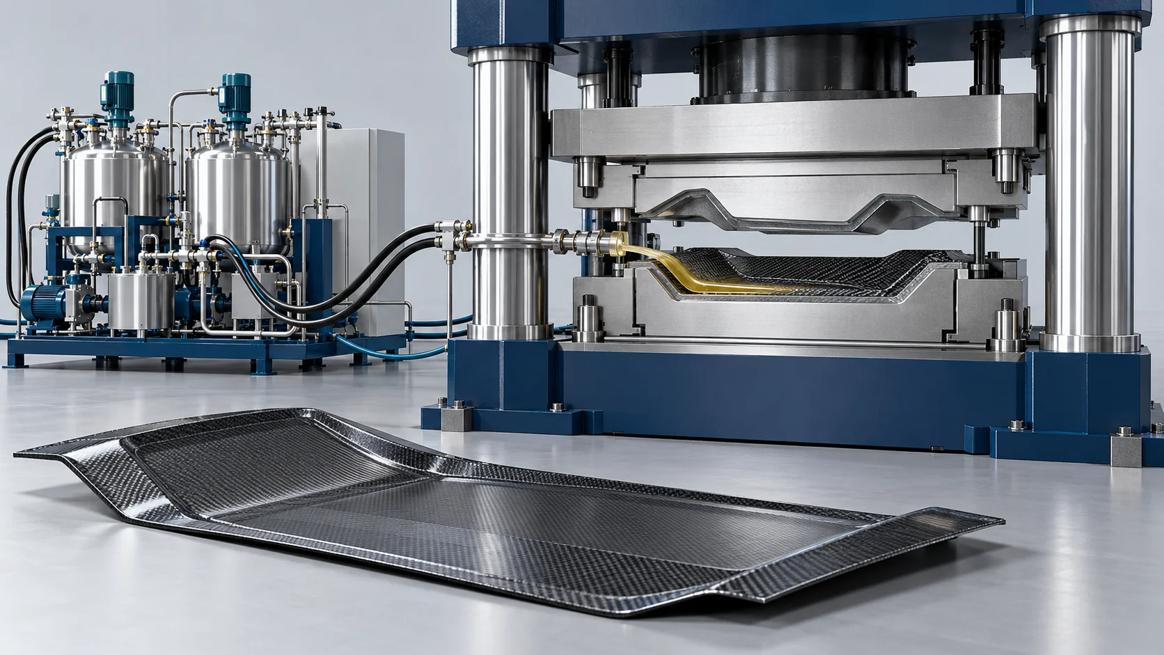
High-Pressure Compression RTM Production Solution
Coordinate resin injection and controlled tool compression for a validated HP-CRTM laminate design.
Configure HP-CRTM Injection and Compression
Coordinate resin distribution through a controlled tool gap with synchronized compression, material-specific cure and part inspection.
Product and material first
Start with the finished-product drawing, material system and acceptance requirements. The process route and equipment configuration are assessed together.
Compare the closed-tool injection route: HP-RTM Production.
Capacity across the whole process
Define output with preparation, forming/reaction, curing, handling and inspection included. The slowest stage and product changes determine practical line capacity.
Carbon-fiber battery trays and floor pans
A large-area HP-CRTM configuration combines carbon-fiber preforms, high-pressure resin metering, surface distribution through a controlled tool gap and synchronized press compression. Metering-circuit pressure is distinct from mold-cavity pressure. The battery-tray reference below describes a specific resin, tool, press and handling arrangement.
Define resin introduction, controlled tool gap, compression and cure as a coordinated HP-CRTM sequence. Separate maximum mechanical capability from allowed process settings, and agree how gap and parallel motion are measured with the selected tool.
From Preparation to Qualified Product
A planning sequence for the specified route. Final settings and acceptance conditions are established through material and part review.
Define compression-assisted filling
Review fiber architecture, resin flow and the intended tool-gap/compression strategy.
Prepare preform and cavity
Load reinforcement and define the initial cavity arrangement and seals.
Meter and introduce resin
Coordinate mixed resin delivery with the defined injection stage.
Information Needed to Configure the Line
Provide these inputs so the equipment range, interfaces and validation plan can be defined.
| Design input | Information required |
|---|---|
| Laminate | Preform, fiber fraction and final thickness |
| Resin | Flow, ratio and reaction window |
| Press/tool strategy | Initial gap, closing profile, sealing and limits |
| Validation | Impregnation, thickness, void and mechanical tests |
Carbon-Fiber Battery Tray: Configuration Reference
These supplied values describe a configured application, not the operating range of every HP-CRTM system. Confirm the material, tooling, load, measurement method and acceptance criteria in the technical agreement.
| Parameter | Value / Unit | Applicable Configuration / Conditions |
|---|---|---|
| Molded Component Surface Area | Up to 3.52 m² (2,200 mm× 1,600 mm) | Oversized structural composite battery trays and floor pans; configuration-specific reference or part acceptance target |
| Hydraulic Compaction Velocity | Up to 300 mm/s | Fast-acting servo press with active parallel leveling; configuration-specific reference or part acceptance target |
| Injection Delivery Flow Output | 20.0 to 300.0 g/s | Continuous variable servo-hydraulic impingement proportioner; configuration-specific reference or part acceptance target |
| Micro-Gap Dynamic Positioning | 0.5 to 2.0 mm (Tolerance ±0.02 mm) | Optical linear scale closed-loop press position feedback; configuration-specific reference or part acceptance target |
| Mold Cavity Evacuation Level | Down to 0.05 kPa (Absolute) | High-speed multi-stage vacuum pump with tool silicone seals; configuration-specific reference or part acceptance target |
| Total Part Molding Cycle Time | Less than or equal to 120 seconds | From preform loading to demolding with fast-cure epoxy; configuration-specific reference or part acceptance target |
Reference Process and Acceptance Conditions
The configured sequence covers preform loading, controlled-gap resin distribution, synchronized compression, in-mold cure and robotic demolding. The supplied example uses a 44 kg tray, a 130°C tool temperature, approximately 75 seconds of cure and a 115-second complete cycle; the stated ceiling is 120 seconds from loading to demolding. These timings depend on the selected fast-cure epoxy, tool and handling sequence.
The supplied 35% weight comparison applies to the specified aluminum tray baseline and composite design. A below-0.5% porosity target requires a defined quantitative inspection method and part acceptance criteria; vacuum level alone does not establish laminate quality.
Core Equipment and Integrated Interfaces
The linked resin-injection system is coordinated with a separately specified press/tool and its motion/control interface.
Coordinate the Equipment With the Process
Evaluate repeatability, handling and acceptance across the full workflow.
Controlled-gap filling
Map resin distribution and compression to the actual tool gap.
Press/feed synchronization
Agree motion, leveling, delivery and interlock records.
Complete-cycle inspection
Separate fill/compression/cure timing and inspect the intended laminate.
Controlled compression interfaces
Tool-gap control, press leveling, resin spreading and fiber compaction are coordinated for the selected preform; zero fiber displacement is not guaranteed.
Related Projects
The battery-tray project is a reference for its HP-CRTM construction and supplied equipment, not every HP-RTM or PCM route.
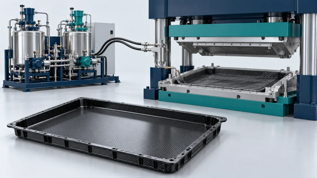
Frequently Asked Questions
Review controlled-gap filling, coordinated equipment and complete-cycle planning.
What distinguishes HP-CRTM from HP-RTM?
What information is needed to plan an HP-CRTM cell?
What is included in the HP-CRTM equipment package?
How is the complete molding cycle defined?
What should be documented for the compression-assisted filling sequence?
Submit Your Production Goals
Share the following for this application: Part/laminate, preform, resin, initial gap, tool/press motion, delivery profile, cure and inspection plan. Our team will reply within one business day. Once requirements are clear, we provide a preliminary proposal within two business days.


