
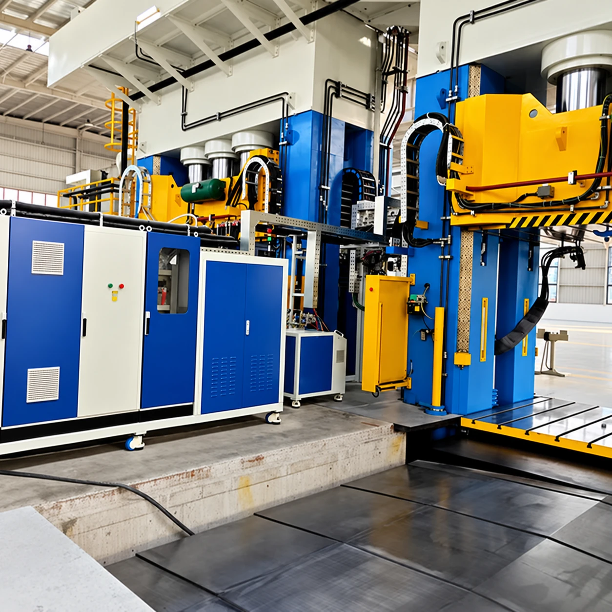
Advanced Composites HP-RTM Solution
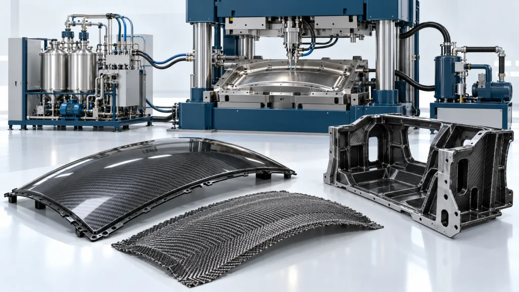
Coordinate high-pressure resin metering and impingement mixing with closed-tool injection, preform handling and cure control for the selected composite part. Image: concept illustration of HP-RTM equipment and a press interface, reconstructed from a source photograph.
Next-Generation Liquid Composite Molding for Structural Lightweighting
Haifeng configures HP-RTM resin conditioning, high-pressure metering and impingement mixing with a closed molding tool, reinforcement handling, cure control and inspection interfaces. Press selection, tooling, resin and site services are defined for the application. Compression-assisted filling is a distinct HP-CRTM route, specified separately.
HP-RTM and HP-CRTM are distinct routes
The main HP-RTM sequence injects mixed resin into a closed tool containing the preform. An initial tool gap and a subsequent compression stroke belong to a separately configured HP-CRTM production solution; they are not required steps in every HP-RTM process.
Tool-Mounted Solvent-Free Cleanout
Tool-mounted mechanical cleanout heads are specified to clear retained mixed resin and cut runners; the tool, resin and cleaning sequence determine the remaining runner and cleaning requirements.
For structural automotive and other specified composite applications, define the reinforcement, resin, tool and complete loading-to-demolding sequence. Supplied sub-3-minute cycle and impregnation references are configuration-specific; internal defects and final properties require the agreed part tests. Map the selected resin-feed package to the actual HP-RTM tool and press. Mass flow, volume-flow packages, mixing pressure and tool vacuum need their own material and measurement basis; the closed-tool route remains separate from compression-assisted filling.
HP-RTM Closed-Tool Injection Workflow
A precision industrial sequence engineered for high-throughput composite part consolidation.
Prepare and load the preform
Prepare the specified reinforcement and load it into the heated tool. Fiber architecture, binder and handling are selected for the part.
Close, seal and evacuate the tool
Close and seal the molding tool. Configure evacuation and leak checks for the preform, resin and cavity design.
Meter, mix and inject resin
Coordinate high-pressure impingement mixing and mixed-resin delivery into the closed tool. Metering-circuit pressure, cavity pressure and flow are specified separately.
Reference Solution Engineering Envelope
Compare the selected production-cell reference with additional HP-RTM metering packages. Each table describes its own configuration; flow basis, material system, electrical scope and auxiliary equipment must be selected together.
Selected Closed-Mold Production-Cell Reference
| Parameter | Value / Unit | Applicable Configuration / Conditions |
|---|---|---|
| Peak Injection Pressure | 12.0 to 20.0 MPa | Servo-hydraulic axial piston proportioning skid |
| Instantaneous Dispensing Output | 10.0 to 250.0 g/s | Continuous variable displacement servo drive |
| Dosing Stoichiometry Precision | Ratio tolerance within ±0.2% | High-pressure Coriolis mass flow closed-loop control |
| Mold Cavity Evacuation Level | Down to 0.05 kPa (Absolute) | Dual-stage dry rotary vane vacuum skid with mold sealing |
| Compatible Fiber Volume Fraction | 50% to 60% (V_f) | Carbon fiber, glass fiber, and hybrid stitched preforms |
| Total Part Molding Cycle Time | Less than 3.0 minutes | Preform loading to demolding with fast-cure epoxy |
Additional HP-RTM Metering Configurations
The following volume-flow packages are additional configuration references. They are separate from the selected HF-HPRTM-250 mass-flow configuration; do not combine their tank, power, flow or accuracy data into one machine specification. Actual output depends on the material system, recipe ratio and viscosity.
| Configuration | Volume-flow reference | Maximum metering/mixing pressure | Equipment power reference |
|---|---|---|---|
| Lower-output package | 6–60 mL/s | Up to 200 bar (20 MPa) | 30–50 kW |
| Mid-output package | 30–250 mL/s | Up to 200 bar (20 MPa) | 40–60 kW |
| Higher-output package | 170–735 mL/s | Up to 200 bar (20 MPa) | 60–70 kW |
| Selection item | Reference and configuration boundary |
|---|---|
| Material compatibility | Selected polyurethane or epoxy systems; wetted components and conditioning are matched to the approved material. For PU, A is polyol and B is isocyanate; epoxy uses the specified resin and hardener. |
| Processing viscosity | 100–1,000 mPa·s at the specified processing temperature. Confirm each component and the selected pump/head operating window. |
| Material vessel options | 15 L, 60 L or 250 L reference options; vessel count, allocation and usable capacity are specified for each circuit. |
| Mixing method and recipe | High-pressure impingement mixing. Specify component order and mass- or volume-ratio basis from the approved material data; verify the selected metering range against that recipe. |
| Electrical supply and load scope | Three-phase 380 V, 50 Hz reference. Incoming current and electrical loads are specified for the ordered package and its auxiliaries; press and site-service loads are scheduled separately. |
| Main-unit envelope | 3,660 × 1,800 × 2,200 mm reference for the supplied configuration; confirm maintenance access, head reach and auxiliary equipment in the project layout. |
| Volume flow versus mass flow | mL/s and g/s are different quantities. Conversion requires component densities at the stated temperature and a defined flow/ratio basis. |
| Pressure boundary | The maximum metering/mixing pressure does not establish mold-cavity pressure, a required operating setpoint or finished-part performance. |
Upstream material preparation can be sized separately. One auxiliary degassing reference uses two 300 L SUS304 material vessels, two 15 L vacuum isolation vessels, 45 r/min vessel agitation and 60 L/min gear-pump transfer. These are auxiliary conditioning/transfer ratings, not mixing-head speed or injection output. Review the HP-RTM equipment configurations and auxiliary-system details.
Core Equipment for This Solution
The injection machine is coordinated with specified material preparation, tool-mounted cleanout, transfer, vacuum and press interfaces; these are not all implied by a dosing skid.
Core Advantages of Haifeng Composite Solutions
Engineering features designed to conquer high scrap rates, lengthy cycle times, and fiber displacement.
High-Pressure Impingement Mixing
Metering and impingement circuits are configured for the selected resin and hardener.
Closed-tool injection interfaces
Metering, tool injection and press holding are coordinated for HP-RTM; compression-assisted filling is separately specified as HP-CRTM.
Vacuum-Assisted Processing
Material degassing and mold evacuation are configured to control air entrapment; part void content requires inspection.
Mechanical Head Cleanout
A tool-mounted mechanical cleanout system is specified; runner and cleaning requirements depend on the tool and resin.
Related Projects
The linked composite project supports its actual resin, part and supplied cell. Verify that configuration before transferring pressure, flow or cycle references.
Production Planning FAQ
Selection, supply scope and validation for this production route.
How does HP-RTM differ from HP-CRTM?
Which resin systems can be processed?
Is mixing pressure the same as mold-cavity pressure?
How are cycle time and part quality validated?
How should the three volume-flow packages be compared with the selected cell?
Are degassing-vessel agitation and transfer flow injection-head specifications?
What inputs are needed for this configuration?
How should volume-flow packages be compared with a mass-flow cell reference?
Request an Advanced Composites Equipment Proposal
Share the following for this application: Resin density/viscosity, shot and filling window, feed-package specification, head, preform/tool, press and vacuum interfaces. Our team will reply within one business day. Once requirements are clear, we provide a preliminary proposal within two business days.


