
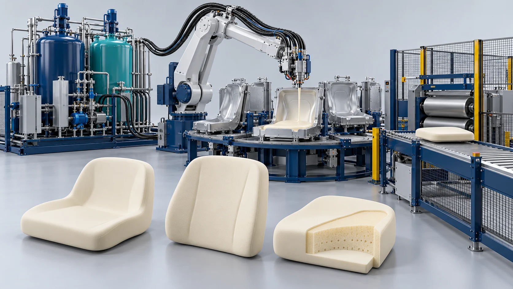
Furniture Seating Three-Component High-Pressure PU Foaming Solution
High-Pressure polyurethane metering for molded furniture cushions and seating, with selectable polyol feeds, four mold/carrier stations and coordinated material and mold conditioning.
Three-Component High-Pressure PU Foaming for Furniture Seating
High-Pressure polyurethane metering for molded furniture cushions and seating, with selectable polyol feeds, four mold/carrier stations and coordinated material and mold conditioning. This is an application-specific reference package; final foam properties and production timing are established with the selected raw materials and tooling.
Selectable Polyol Formulations
Separate A1 and A2 circuits accommodate regular and filled polyol recipes with isocyanate in circuit B. Recipe selection, circulation and material compatibility are verified for the intended foam.
Matched Tooling and Temperature Control
Four molds and carriers, a 3.5 m jib, a 250 L premixer and mold/material temperature-control auxiliaries form the reference workcell. This configuration uses a 180° jib rotation.
Define material preparation, metering, mixing, tooling, utilities and acceptance as one project configuration. The supplied four-mold reference is distinct from a separately specified robot or carousel line.
High-Pressure Furniture Foam Molding Process
Coordinate material conditioning, recipe calibration, manual pouring, mold curing and cleaning across the four reference stations.
Condition A1, A2 and B
Prepare the regular and filled polyols separately. Use the premixer and A2 agitation/circulation to condition the selected additive formulation.
Prepare the Four Mold Stations
Apply the selected release system, set the agreed mold temperature and check cavity, insert, venting and carrier access before pouring.
Select the Active Polyol Feed
Select A1 or A2 with the B isocyanate circuit, load the recipe, and verify component discharge and ratio. The 2A+B notation does not establish simultaneous three-stream mixing.
Reference Equipment and Tooling Parameters
Values below describe the supplied high-pressure technical agreement. Final selection and acceptance follow the approved configuration and actual-material trials.
| Parameter | Reference configuration | Engineering basis |
|---|---|---|
| Working material tanks | 3 × 250 L: A1, A2 and B | A1: regular polyol; A2: filled/flame-retardant polyol; B: isocyanate |
| Tank operating-pressure reference | Approximately 0.4 MPa | Tank operating pressure is separate from mixing pressure; final vessel design and nameplate govern |
| Metering and mixing | High-pressure piston metering and hydraulic self-cleaning impingement head | 2A+B arrangement with selectable A1/A2 polyol feeds |
| Injection-pressure reference | 10–25 MPa | Reference high-pressure mixing range; separate from tank and hydraulic pressures |
| Adjustable combined discharge | 0.13–1.3 kg/s | High-pressure agreement range; verify for the selected materials and recipe |
| Rated combined discharge | Approximately 1.2 kg/s | Specified combined-output reference |
| Working discharge target | At least 1.0 kg/s | Verify the stated working-flow requirement during FAT |
| Recommended shot in the reference | Approximately 2 kg | Other shot weights require process sizing; the low-pressure 2–12 kg range is not transferred |
| Polyol:isocyanate ratio | 100:(30–100) | Adjustable reference; calibrate for the selected materials and recipe |
| Metering accuracy / repeatability | ±1% / ±0.5% | Specified reference values; verify by agreed gravimetric discharge tests |
| Pouring jib | 3.5 m length; 180° rotation | Rotation confirmed by the owner; 3–4 m length customization in the reference |
| Mixing-head working height | Approximately 1.5–2.0 m | Adjustable column; confirm access and mold clearance |
| Premixing unit | 250 L; disperser and wall-scraping agitator | Prepare or condition the filled polyol before transfer to A2 |
| Mold temperature reference | 40–50°C | Final process setpoint is formulation- and tooling-dependent |
| Demolding-time reference | Approximately 7 min | Process reference, not a guaranteed finished-part production rate |
| Temperature-control auxiliaries | 3 HP nominal chiller unit; 12 kW mold temperature unit | Chiller HP rating is not a stated net cooling-capacity value |
| Automatic refill reference | Approximately 40 L/min | Multi-point level signals coordinate refill and extreme-level interlocks |
| Machine and jib working zone | Approximately 8 × 6 m | Confirm the complete layout with maintenance and mold-handling access |
| POL and ISO pump references | 30 cc/rev each; approximately 11 kW POL and 5.5 kW ISO drives | These are the stated POL/ISO circuit references; final A2 pump details follow the approved schedule |
| Hydraulic power unit | 7.5 kW; approximately 120 L oil reservoir | Power for mixing-head actuation and mechanical cleanout |
| PLC and operator panel | Industrial PLC with 9-inch HMI; at least 99 stored recipes | Brand and final I/O schedule confirmed for the project |
| Mold-carrier tilt | 0–90° adjustable; four carriers | Confirm tooling mass, locking and assisted opening against the mold drawings |
| Target foam density | 50–60 kg/m³ in the reference brief | A formulation/process target rather than an equipment-guaranteed foam property |
| Electrical supply | 380 V ±10%, 50 Hz, three-phase | Total installed power follows the final complete load schedule |
| Compressed air | At least 0.6 MPa; dry and oil-free | Final consumption and connections follow the site utility schedule |
Four-Mold Reference Package
| Parameter | Reference configuration | Engineering basis |
|---|---|---|
| Mold 1 | 1,800 × 900 × 840 mm | Steel reinforcing frame with aluminum forming cavity |
| Mold 2 | 1,460 × 780 × 400 mm | Cast aluminum tooling |
| Mold 3 | 800 × 1,000 × 820 mm | Cast aluminum tooling |
| Mold 4 | 890 × 890 × 740 mm | Cast aluminum tooling |
Dimensions are internal forming-cavity references, stated as width × depth × height. External dimensions, part geometry, charge weight, mounting and temperature-control connections follow the approved tooling drawings. Four carriers are arranged within the confirmed 180° pouring envelope.
Filled Polyol Preparation and Compatibility
The supplied reference proposes melamine additions up to 30% with particle size up to 100 μm, or expandable graphite additions up to 20% with particle size up to 150 μm. These are separate material-design references, not a universal acceptance envelope or finished-foam fire classification. The low-pressure brief states addition percentages relative to polyol; the final high-pressure formulation basis must be agreed with the material supplier.
Premixing, low-speed A2 agitation and recirculation address suspension and settling. Select pump wear protection, flowmeter suitability, filter openings and cleaning procedures using actual particle distribution, viscosity and raw-material trials. Filtration must protect the equipment while retaining the intended formulation. Filled-polyol suitability is verified before final equipment selection.
Commissioning and Factory Acceptance
Use the agreed raw-material batch to calibrate each active component by weight, verify combined output and ratio, and check shot repeatability. Trial the selected filled polyol for circulation, settling, filtration and cleanout, then confirm mold temperature, filling, cure and demolding on the actual tooling. Record the agreed operating conditions and acceptance results.
Delivery can include installation guidance, operator and maintenance training, equipment drawings, operating documentation and authorized remote PLC diagnostics. Exact service and warranty scope follows the confirmed supply agreement.
Equipment for This Solution
Existing application machines illustrate the high-pressure equipment family. Their own component counts and ratings do not define this three-circuit furniture configuration.
Equipment Features for the Furniture Workcell
Coordinate the selected material formulation, mixing route, tooling and production workflow.
Recipe Selection
Stored recipes coordinate the selected polyol circuit, isocyanate flow and injection settings.
Filled-Polyol Conditioning
A2 agitation, circulation and premixing are sized for the actual filled-material properties and trial results.
Material and Mold Conditioning
Jacketed tanks, heat exchange and mold temperature control support an agreed process window.
Defined Acceptance Tests
Gravimetric calibration and tooling trials establish discharge, ratio, repeatability and part-processing conditions.
Related Project Case
Review the production configuration, delivery and results.
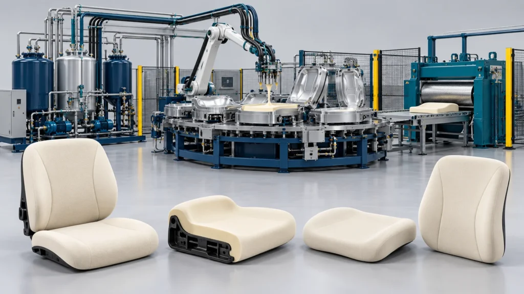
Office Chair Foam Cushion Line Project in Morocco
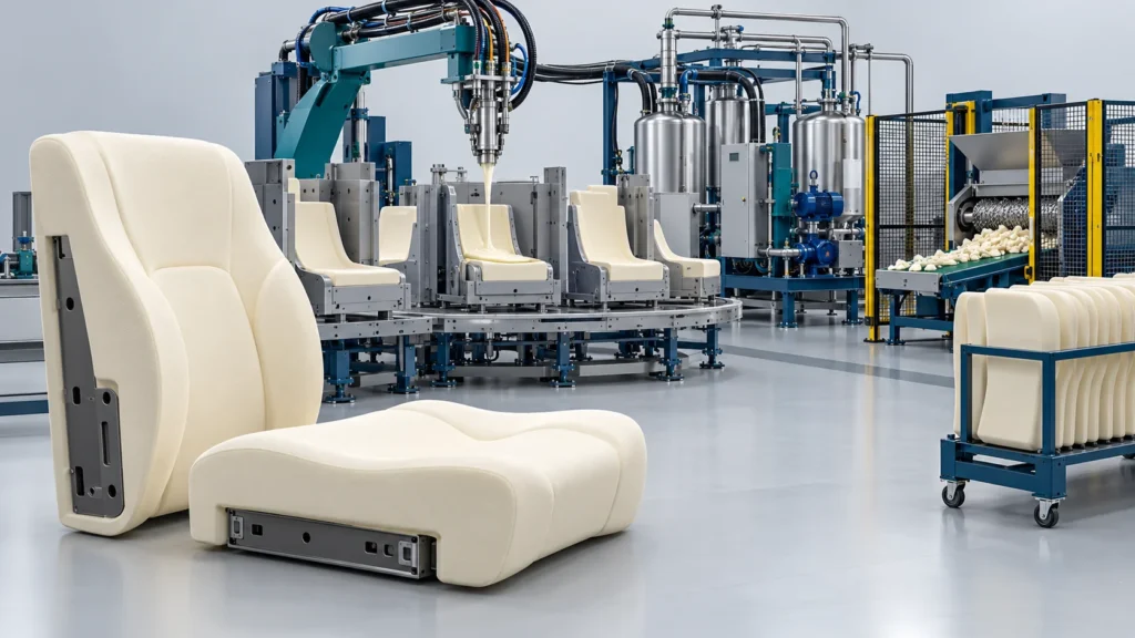
Auditorium Theater Seating PU Line Project in Kazakhstan
Frequently Asked Questions
Clarify configuration, filled-material trials, pouring access and performance verification.
Does three-component mean that A1, A2 and B always mix simultaneously?
Are output, density and a seven-minute cycle guaranteed for every formulation?
Can this system process melamine- or graphite-filled polyol?
What is the pouring jib rotation?
Does the four-mold package include a robot or automated carousel?
How should low- and high-pressure routes be compared?
How is the high-pressure mixing head cleaned?
Discuss Your Furniture Seating Production
Send part and tooling drawings, polyol/isocyanate data, additive loading and particle sizes, shot weights, desired production rate and factory utilities to define the high-pressure configuration.


