Refrigerator cabinet foaming succeeds or fails long before the first pour. The fixture that positions the cabinet shell and liner, the path the liquid mix takes through the cavity, and the number of stations that hold the part under constraint determine whether the line produces uniform insulation or recurring voids and bowed panels. For production managers planning a new or upgraded line, those fixture and station decisions should be settled before the machine order is locked, because moving a fixture or adding a cure station after installation costs far more than changing a pump or a mix head.
For the wider production route and equipment interfaces, explore our refrigerator and freezer foaming systems.
What Cabinet Foaming Fixtures Actually Do
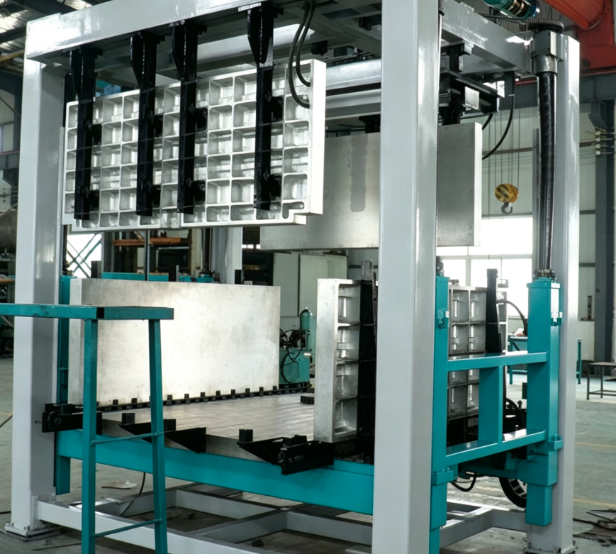
A cabinet foam fixture is more than a clamp. It locates the outer shell and liner in the correct cavity gap, resists the pressure generated during foam rise, seals the fill area so the mix does not escape, and keeps the assembly constrained while the foam builds strength. If the fixture deflects or the liner shifts, two things happen: the cavity gap changes across the cabinet, and the foam density no longer matches the intended fill. Thin metal panels show this as visible bowing after demold, even when the metering ratio was correct.
For the cabinet, insulation material and equipment interfaces, review the refrigerator cabinet foaming solution.
| Fixture input | What it controls | Why it matters for cabinet foaming |
|---|---|---|
| Shell and liner location | Cavity width | Keeps insulation thickness and density consistent |
| Clamping force and frame stiffness | Fixture deflection during rise | Prevents side wall bowing and resin-rich edges |
| Mold or plug temperature | Wall surface reaction | Stabilizes skin quality and demold release |
| Vent positions and seal condition | Air escape path | Reduces trapped air at top corners and liner back |
| Pre-fixed part location | Fill access | Prevents inserts from moving during injection |

Define the Fill Path Before Placing the Machine
Injection point placement should follow the cabinet geometry, not the convenience of the mix head. A wide side-by-side cabinet may need bottom or mid-height injection so the rising foam pushes air toward vents at the top corners. A narrow under-counter cabinet may fill reliably from a single point if the flow distance is short and the rise profile is stable. When the fill path is wrong, the line shows a repeating signature: dense material near the injection point, an under-packed corner, and voiding behind the liner.
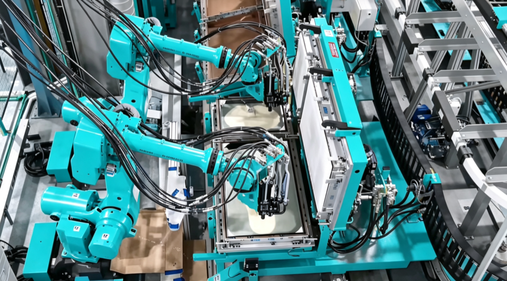
Once the cavity map is defined, shot weight sets the pour window. Large multi-door cabinets can require several kilograms of rigid foam in one rise, while compact bar cabinets may be under one kilogram. The fill time must stay shorter than the cream time, so a fixture plan is only viable if the metering unit can deliver the required shot without pushing beyond its stable output band. The practical check is to convert cavity volume and target free-rise density into shot weight, then compare that number with the machine’s usable pour rate.
Cavity volume and target density determine how much material the metering unit must deliver before the mix begins to rise. <How To Calculate Shot Weight In Polyurethane> covers the calculation inputs and the common mistakes that distort shot planning.
A high-pressure unit such as the HF-HPM-1A1B-Refrigerator from Haifeng Polyurethane Machinery is designed around cabinet-class work, with a pour rate of 50 to 1200 g/s, 10 to 18 MPa mixing pressure, and 100/150 L tanks. The machine selection still follows the fixture and station plan. Buying the largest output first can overload a compact cavity with a shot that is too fast to vent.
Plan Stations Around Cure and Demold Time
The station count is not the same as machine count. A cabinet line needs enough holding stations after the pour to cover demold time without stopping the metering unit. Station count equals cure time divided by the target takt time, plus buffer positions for loading and inspection. If the fixture releases the part before the foam has developed enough strength, the cabinet can continue to move after leaving the mold, and that movement becomes the next process problem.
For example, if the demold time is eight minutes and the required takt is two minutes per cabinet, at least four cure stations must be available after the pour. That number changes if a closed mold is used, if the liner preheat is higher, or if the formulation is adjusted. The point is to keep the metering machine producing while the foam is still constrained, rather than waiting for one slow fixture to release.
Use Rise Time to Place Injection Points
Rise time controls how much of the cavity is filled by liquid flow and how much by expansion. This distinction matters for injection point placement. If rise time is short, the foam thickens while the material is still moving through the cavity. The result can be a dense leading edge and an under-packed far corner. If rise time is long, air has more time to escape, but the fixture must hold the assembly longer before it reaches full fill. For cabinet foaming, the station planner needs the formulation’s cream time, gel time, and rise time, not only the machine output.
Rise time controls how much of the cavity must be filled by flow and how much by expansion, which changes where injection points belong. <The Role Of Rise Time In Polyurethane Foaming> covers the practical interpretation of rise time on a production line.
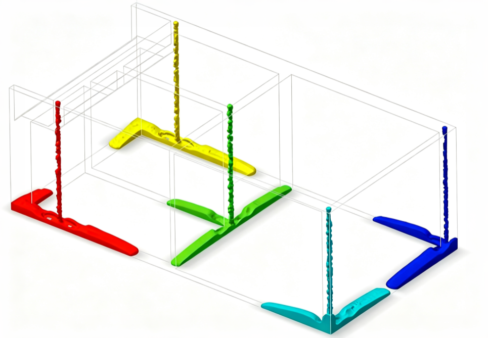
Control Shrinkage Through Fixture Release Timing
After demold, the cabinet continues to cool. If the fixture releases the part while the foam core still carries residual reaction heat, the outer shell, liner, and foam can contract at different rates. The result may not appear at the demold station; it shows later as bowed side panels, pulled-back liner corners, or a changed gap between shell and liner. The hold station therefore needs to keep the part constrained until the material has passed the point where post-demold movement can be controlled. This is less about building a longer conveyor and more about deciding when the fixture stops influencing the part.
Shortening the holding sequence without changing the chemical system can transfer shrinkage problems from the mold to the warehouse. <Causes Of Shrinkage In Polyurethane Foam How To Control It> covers the causes and the process levers that keep post-demold movement within limits.
Validate the Fixture and Station Plan Before Acceptance
Before accepting a layout, run a focused trial on the actual cabinet model with the planned fixture. Do not accept a machine test on a generic mold as proof that the cabinet will fill. The trial should show whether the fixture holds the cavity gap during rise, whether the injection points produce a clean fill pattern, and whether the cabinet releases without post-blow or surface marking. Cut samples from more than one cabinet and inspect the far corner, the liner back, and the area near the vent.
| Check | Pass condition | If it fails |
|---|---|---|
| Fixture deflection | Cavity gap repeatable across full rise cycle | Increase frame stiffness or add clamps |
| Fill pattern | No voids at far corners and liner back | Adjust injection points or vent position |
| Demold release | Part exits without post-blow or liner lifting | Extend hold time or review release agent |
| Changeover | Next model reaches steady state without trim damage | Add quick-change locating features |
| Shot weight | Metering output fills cavity within cream time | Rebalance shot mass and pour rate |
Next Step for Your Fixture and Station Plan
Send the cabinet dimensions, shell and liner materials, target shot weight or cavity volume, current demold time, and the daily model mix to the team. Those inputs are enough to review injection positions, fixture pressure points, and station count against the process before the machine specification is fixed. Contact us at Info@chinahaifeng.com or WhatsApp: 86 13566296633.
FAQ
Does refrigerator cabinet foaming need high-pressure or low-pressure equipment?
High-pressure mixing is usually the safer default for cabinet lines because it produces a fast, homogeneous mix that can fill a large cavity before viscosity builds. Low-pressure machines can work for compact cabinets or slower lines, but they are more sensitive to shot size and mixing consistency. Match the equipment to the required pour rate and shot weight, not to a preference for one technology. The fixture plan stays the same; the machine must be able to deliver the shot within the cream time.
How many stations do we need?
Start with demold time divided by takt time. If a cabinet needs eight minutes before demold and the line must produce one cabinet every two minutes, four cure stations must follow the pour. Add one or two buffer positions for loading, inspection, and model changeover. The exact number depends on the formulation, preheat, and whether the fixture remains closed during cure. The goal is to keep the pouring machine running while parts are still constrained.
Can we reuse existing fixtures when changing cabinet models?
Sometimes, but not automatically. A fixture built for one shell geometry may have the wrong cavity gap, vent position, or clamping force for another model. Quick-change locating features help, but they do not fix a deflection problem. Before reusing a fixture, compare the shell and liner dimensions, injection point, and fill path. If the geometry changes enough to alter the rise pattern, modify the fixture rather than accepting higher scrap.
Where should injection points be located?
Place them so the rising foam pushes air toward the vents, not toward a dead corner. Bottom or mid-height injection works for many tall cabinets; a single point may be enough for a narrow cabinet if the flow distance is short. The only reliable answer comes from a fill trial on the actual cabinet. Injection point placement should be confirmed before the station layout is fixed, because moving the mix head later changes the fixture and the safety zone.
If you’re interested, check out these related articles:
Causes Of Shrinkage In Polyurethane Foam How To Control It
The Role Of Rise Time In Polyurethane Foaming
How To Calculate Shot Weight In Polyurethane
How Polyurethane Rollers Are Made From Casting To Cure