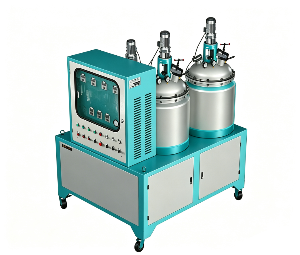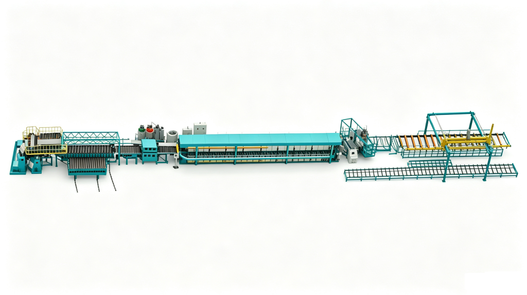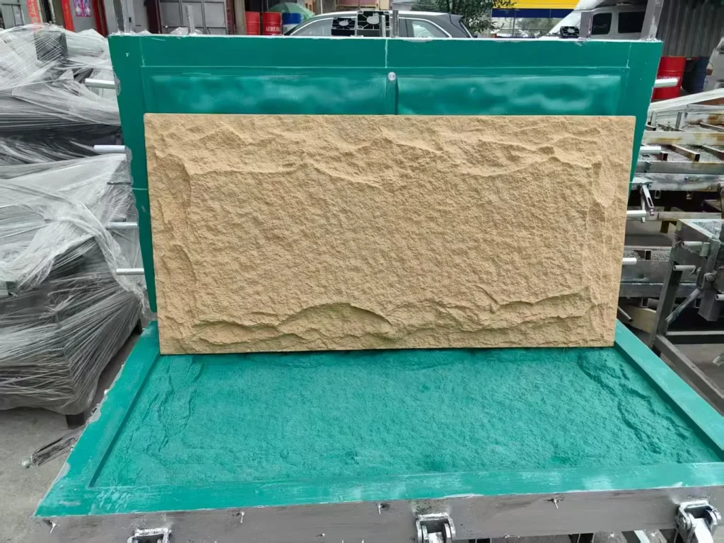

A panel order book that mixes 40 mm cold-room walls with 150 mm roof panels will not run on one line setting, and the cost of pretending otherwise shows up as density drift, edge voids, and a belt gap that never quite settles. PU panel line planning for mixed sizes and thicknesses starts from one quantity: the mass of foam the line must deliver per minute at each thickness. Thickness sets that mass flow, width and length set the handling and the cut-off, and the span between your thinnest and thickest panel decides whether a continuous double-belt line, a batch press, or both is the honest answer.
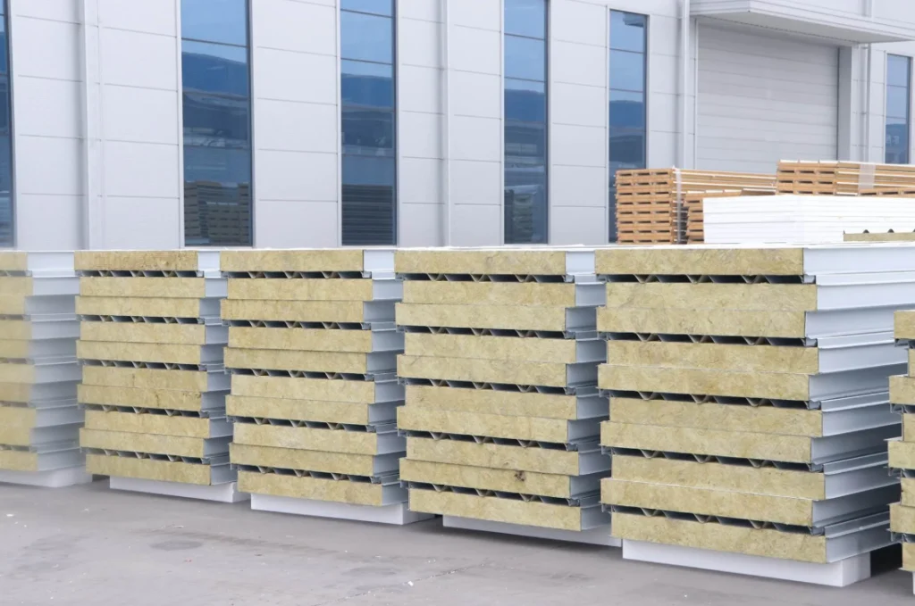
Why thickness changes the line before size does
On a continuous line the foam is deposited onto the lower facing at a fixed point and expands as the facings travel. The mass entering the belt each minute has to match the volume of core leaving it. Core volume per minute is line speed multiplied by panel width multiplied by core thickness. Double the thickness at the same speed and the line needs double the mass flow, or half the speed.
A 30 mm core and a 200 mm core are therefore two different processes on the same machine. In a thin core the foam has to spread across the full width inside a narrow gap before it gels, so edge voids and width-wise density variation are the failure mode to watch. In a thick core the reaction heat has further to travel to reach a facing, so the peak temperature at the centre rises steeply as thickness increases. That shows up as scorch, as over-expansion pressing against the belt, and as a core that keeps moving after cut-off.
A thick core that keeps shrinking after cut-off usually started with an exotherm problem at the centre, not with the facings. <Causes Of Shrinkage In Polyurethane Foam How To Control It> covers how shrinkage develops in polyurethane foam and the process levers used to control it.
Length and width change the handling, not the chemistry. Cutting, stacking, edge profiling and side sealing all react to panel size, and a line that handles 12 m panels needs the floor space and the saw travel that a 6 m line does not. Thickness is the variable that reaches back into the metering unit.
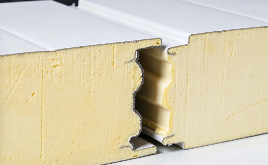
Continuous double-belt or batch press for your thickness range
Both architectures are sold as panel lines, and the specification sheets overlap enough that the difference is easy to miss. The table below sets out where they actually diverge, using published specifications for the two line types.
| Decision input | Continuous double-belt line | Batch platen press | What decides it |
|---|---|---|---|
| Thickness band | 30 to 200 mm on the HF-CLPS-Continuous | 20 to 300 mm on the HF-CLPS-Batch | Your thickest standard panel and how often it runs |
| Output basis | Stepless 1 to 15 m/min | 3 to 10 min per panel cycle | Whether you plan in square metres per shift or panels per shift |
| Changeover | Belt gap, side seals, pour point and speed reset | Mold or spacer change | Number of thickness bands touched per week |
| Run length | Long runs of one specification | Short runs, specials and samples | Order book pattern, not machine capability |
| Length control | Flying cut-off saw from an encoder | Mold frame sets length | How much your lengths vary against your thicknesses |
| Typical fit | One to three dominant thicknesses | Many bands, thick cores, development work | The mix, which the datasheet maximum never shows |
The decision rule is arithmetic rather than preference. If most of your annual square metres sit in one to three thickness bands and each production run lasts long enough that a belt reset is a small fraction of the run, the continuous line carries the lower cost per square metre. If the order book is wide and short, with frequent length changes, thick cores, or development samples, the batch press absorbs that variety with a mold change instead of a full line reset. A plant that sells both standard wall panels and thick specialty cores often runs a continuous line for the volume and a batch press for everything the line cannot run economically.
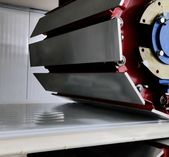
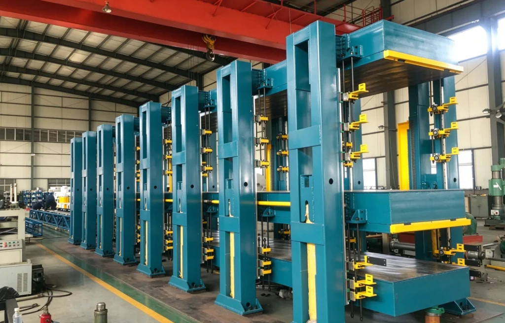
Calculating the pour rate your thickness range demands
The relationship is short enough to check on one line of paper:
mass flow (kg/min) = line speed (m/min) × panel width (m) × core thickness (m) × core density (kg/m³) × packing factor
The packing factor is the molded density divided by the free-rise density for your system. It comes from your own formulation trial, not from a catalogue, and it changes when the foam system changes.
Take a 1.2 m wide panel with a 50 mm core, a specified core density of 40 kg/m³, a packing factor of 1.08, and a line speed of 3 m/min. Volume per minute is 3 × 1.2 × 0.05, which is 0.18 m³/min. Multiply by 40 for 7.2 kg/min, then by 1.08 for about 7.8 kg/min. Now run the same line at 150 mm without changing anything else: volume rises to 0.54 m³/min, and the required mass flow becomes about 23.3 kg/min.
That single comparison explains most of the friction in mixed-thickness planning. A metering unit rated at 15 kg/min cannot hold 3 m/min at 150 mm. To stay inside 15 kg/min at that thickness, the line has to drop to roughly 1.9 m/min. Either the thick panels run slower, or the metering capacity has to grow, or those panels belong on a different machine.
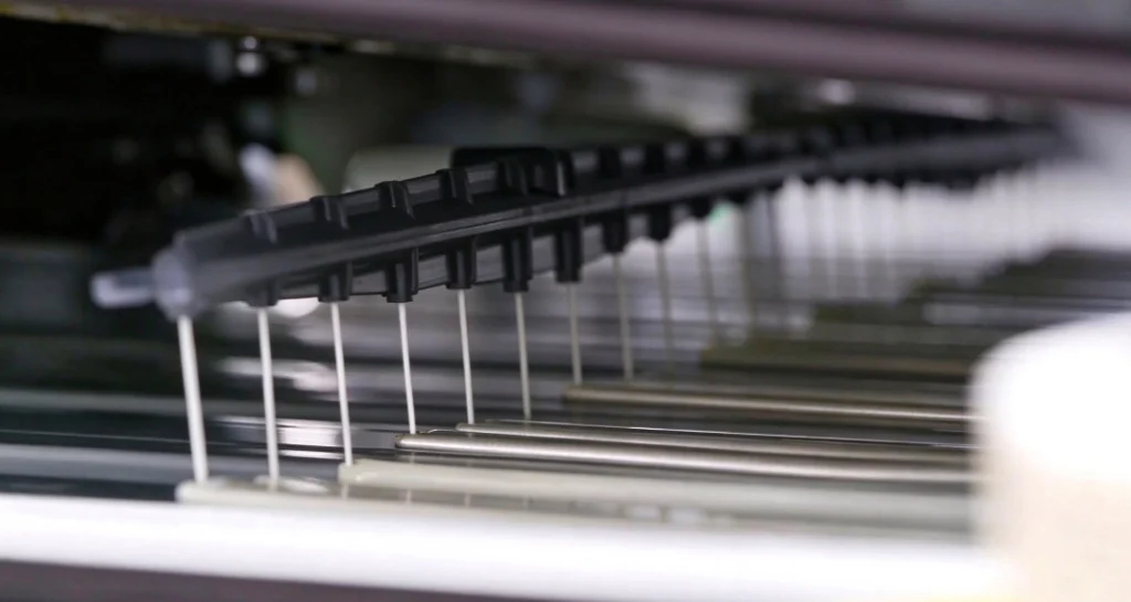
The thickness band your machine can cover
Because mass flow scales with thickness at a fixed speed, the ratio between your thickest and thinnest panel sets the output turndown the metering unit must deliver. A 30 to 200 mm range is a ratio of about 6.7 to 1. Check that the machine’s usable output range covers that ratio at the speeds you actually intend to run. A unit that meets the maximum output figure but cannot meter steadily at the low end will give you poor density control on thin panels, which is the opposite of what the datasheet implies.
Converting the arithmetic into shot weight for a batch press
For a press, the same formula gives the shot weight per mold. A 2.4 m by 1.2 m panel with an 80 mm core at 40 kg/m³ and the same 1.08 packing factor needs 2.4 × 1.2 × 0.08 = 0.2304 m³, then 9.2 kg, then about 10 kg per shot. At a 10 minute cycle that is six panels an hour from one mold position; at a 3 minute cycle it is twenty. The cycle time, not the pump, sets press output once the shot is inside the metering range.
Batch work turns the same arithmetic into a per-mold number, and the number has to include the packing factor or the press will run light. <How To Calculate Shot Weight In Polyurethane> covers how shot weight is calculated in polyurethane processing.
What changes on the line when the thickness changes
A thickness change is a sequence, and skipping a step in it produces a fault that looks like a formulation problem. Work through these in order.
- Set the belt gap or platen spacing to the core thickness plus both facing gauges, then check parallelism across the full width. A gap that is out by half a millimetre across 1.2 m produces a density gradient you will spend a week blaming on the foam.
- Change the side seals. They are thickness-specific parts, and a seal left over from the previous run opens a flash path at the edge where density falls away.
- Move the pour point and the laydown pattern for the new thickness, so the foam reaches both edges before it gels.
- Reset line speed against the new mass flow figure from your own calculation.
- Check the reaction timing against the travel distance from the pour point. If the cream time is long relative to the distance the facing travels before expansion, the foam is carried forward as a liquid band and thickness control suffers.
- Re-verify cut-off length and squareness on the first three panels, because the encoder reference moves with the gap.
- Run first-panel checks: core density at three points across the width, thickness at five points along the length, facing adhesion, and dimensional change after 24 hours.
The cream time you inherit from the foam system sets how far the liquid band travels before it starts to expand, and that distance has to fit the gap between the pour point and the belt. <The Role Of Rise Time In Polyurethane Foaming> covers how rise time behaves in polyurethane foaming and why it matters for line settings.
Put a cost on the change before you accept the schedule. Take a 90 minute changeover on a line running at 3 m/min: the change costs 270 m of nominal output. Compare that with the run length planned for the new thickness. If the run is shorter than a few multiples of that figure, the change is consuming the margin the order was supposed to earn, and the batch press or a second line starts to look cheaper than it did on the quotation.
Facings, edge details and cut-off length
Facings do more than close the panel. Metal facings act as a heat sink and pull reaction heat out of the core, aluminium foil less so, and paper honeycomb behaves differently again because it wets out and holds foam at the interface. Continuous panel lines are commonly specified to run colour steel, aluminium foil and paper honeycomb faces, and each combination needs its own facing preheat setting and its own adhesion check. Facing gauge also belongs in the belt gap calculation, which is why a facing change can disturb a thickness setting that was previously stable.
Edge detail is the variable buyers underestimate. A tongue-and-groove edge, a lap edge and a plain edge each need different side tooling, and switching edge type can take longer than switching thickness. If your catalogue carries several edge profiles, count that as a changeover in the same way you count a thickness change.
Length control splits along the same line as everything else. A continuous line cuts on the fly from an encoder, so length is a setting. A batch press has its length built into the mold frame, so length is a tooling item. If your lengths vary more than your thicknesses, the press route is usually the simpler plan.
Product requirements sit in the standards rather than in the line specification. EN 14509 sets the specification for factory-made self-supporting double-skin metal-faced insulating panels [1], and EN 13165 covers factory-made rigid polyurethane foam products for buildings [2]. Declared thermal performance is measured by heat flow meter methods under ISO 8301 [3]. None of these documents tell you what a given line can hold at 3 m/min. They tell you what the finished panel has to demonstrate.
Where the specification stops and your trial starts
Published line data is a statement about a machine class, not about your product. The records below come from Haifeng Polyurethane Machinery’s published panel line specifications, and each row has a limit on what it can legitimately support.
| Record | Conditions it was observed under | What it can support | What you must not infer |
|---|---|---|---|
| HF-CLPS-Continuous, 30 to 200 mm, 1 to 15 m/min | Manufacturer’s published line specification | The line class covers that thickness band and speed band | That one configuration runs both ends of the band at full speed |
| HF-CLPS-Batch, 20 to 300 mm, 3 to 10 min per panel | Manufacturer’s published line specification | The batch route extends beyond the continuous band | That a 300 mm panel is commercially sensible per square metre |
| HF-HPM-2A2B-SandwichPanel, 300 to 2200 g/s | Published pour rate for the panel foaming machine | The output envelope available for continuous panel pouring | That pour rate equals finished line output after losses and cut-off |
| Dynamic metering accuracy within 0.3 percent of full range | Published machine specification | Ratio control capability of the metering system | That density is uniform across a 1.2 m width |
| EN 14509:2013 product specification [1] | European product standard for factory-made panels | The product framework your panels will be assessed against | That a compliant line produces compliant panels without product testing |
The last row matters most. A line can be built to a sound specification and still produce panels that fail a product assessment, because the gap between machine capability and product conformity is closed by your own trials, your foam system, and your process records. Treat every published figure as an input to a calculation you run yourself.
What to send before a line proposal
A layout proposal is only as good as the inputs behind it. These six items turn the conversation from preference into arithmetic.
| Field | What to send | Why it changes the layout |
|---|---|---|
| Thickness list with volume share | Every thickness you sell, with annual square metres for each | Sets the output turndown and the number of changeovers per month |
| Width and length range | Minimum and maximum panel width, maximum length, cut-off tolerance | Sets belt width, saw travel and stacking arrangement |
| Foam system and density | PUR or PIR, specified core density, free-rise density from your trial | Fixes the packing factor and the mass flow at each thickness |
| Facing types and gauges | Steel, foil, honeycomb, facing thickness | Sets belt gap, preheat and the adhesion check |
| Edge detail | Tongue and groove, lap or plain, and how many profiles you carry | Sets side tooling, often a longer changeover than thickness |
| Output basis | Square metres per shift by thickness, shifts per day | Decides continuous, batch, or a combination of the two |
Send your thickness list first
The fastest way to get a layout that fits is to send the mix rather than the maximum. Tell us the thickness list with the annual square metres behind each one, the width and length range, the facing types and gauges, the foam system with its specified and free-rise density, the edge profiles you carry, and the square metres per shift you need by thickness. With those six in hand, the output calculation and the changeover count can be worked through before any equipment is proposed, and the continuous-or-batch question answers itself.
Contact us at Info@chinahaifeng.com or on WhatsApp at 86 13566296633.
FAQ
Can one continuous line run both 30 mm and 200 mm panels?
The thickness band on a continuous panel line can span that range, and lines of this class are specified from 30 to 200 mm. The constraint is output, not the gap. At 200 mm the mass flow per metre at a given speed is roughly 6.7 times the 30 mm value, so one metering head cannot hold the same line speed at both ends. Most plants run the thick end slower, or keep the thickest panel on a batch press. Run your own mass flow calculation before accepting a single-line proposal for the full range.
When is a batch press better than a continuous line?
When the order book is wide and short. A batch press covers 20 to 300 mm with a 3 to 10 minute cycle per panel, and a thickness or length change is a mold or spacer change rather than a full line reset. If you run many thickness bands, frequent length changes, thick cores or development samples, the press absorbs that variety at lower risk. If most of your volume sits in a few thicknesses in long runs, the continuous line wins on cost per square metre.
How do I verify a new thickness setting on the first panel?
Check four things before the second panel runs. Core density at three points across the width, thickness at five points along the length, adhesion at the facing interface, and dimensional change after 24 hours. If edge density runs below the centre, the pour pattern or the side seal is wrong for that thickness. If adhesion fails, inspect facing temperature and surface condition before touching the foam ratio.
What drives density variation across the panel width?
Foam that has further to travel to reach the edges arrives later and at lower pressure, so the edges end up lighter than the centre. The gap between facings, the pour point position and the condition of the side seals set how far the foam must flow. A gap that is not parallel across the width produces the same symptom on one side only. Measure at three points across the width before changing the formulation.
References
[1] EN 14509:2013, “Self-supporting double skin metal faced insulating panels. Factory made products. Specifications,” CEN, 2013.
[2] EN 13165:2012, “Thermal insulation products for buildings. Factory made rigid polyurethane foam (PU) products. Specification,” CEN, 2012.
[3] ISO 8301:1991, “Thermal insulation. Determination of steady-state thermal resistance and related properties. Heat flow meter apparatus,” ISO, 1991.
If you’re interested, check out these related articles:
Measuring Polyurethane Foam Resilience A Practical Test Guide
What Is Spray Polyurethane Foam Composition And Application