Flow marks on polyurethane parts rarely mean the material itself has failed. In most cases, they are a processing signature: the material started to cure, chill, or lose pressure before the mold cavity was completely filled and the flow fronts fully knitted. Once you read the defect pattern correctly, the fix is usually a controlled change to shot weight, temperature, mixing, or pour sequence rather than a full reformulation.
What Flow Marks Actually Are
In cast polyurethane and microcellular parts, a flow mark is a surface witness line that appears where two flowing fronts meet and do not fully merge, or where a thin skin is deposited during filling and then covered by later material. The mark can show as a dull streak, a raised ridge, a hairline knit line, or a cloudy band running in the pour direction.
The common mechanism is premature gelation or cooling at the moving front. Polyurethane is not a stable melt in the thermoplastic sense; it is a reacting system. If gelation begins while material is still traveling through the cavity, the front loses the ability to wet and merge with adjacent material. The result is a visible boundary even when the part is structurally sound [1][2].
The Root Causes Behind Flow Marks
1. Cold mold or cold material. When the tool is too cold, the outermost layer of polyurethane can thicken before filling is complete. Later material flows behind that skin and creates a flow line at the boundary.
2. Premature gelation. If cream time, gel time, or pot life is too short for the fill path, the material thickens while it is still moving. Gel time and rise time are related but not interchangeable measurements. A system that gels before the cavity is fully packed will frequently show knit lines or surface streaks.
3. Short shot or insufficient fill weight. A cavity that is filled to the edge of the design volume but not fully packed can leave flow marks at the last point of fill. This is especially easy to misread because the part may still look complete.
4. Stop/start pouring or uneven discharge. If the pour rate changes during the fill, or the operator stops and restarts the pour, each restart deposits a new skin. Those interruptions often appear as concentric or directional marks.
5. Air entrapment and poor venting. Air trapped at the flow front prevents the material from merging cleanly. Flow marks then appear near vents, ribs, or sharp transitions in the cavity.
6. Metering or mixing drift. Small deviations in the A/B ratio, worn mixing-head elements, or inadequate shear can leave partially mixed streaks that appear as surface irregularities.
If a short shot is suspected, confirm the actual fill weight against the cavity volume before changing temperatures or catalyst levels. How To Calculate Shot Weight In Polyurethane covers the calculation step by step.
When the defect is a distinct knit line at the meeting point of two fronts, early gelation is usually more important than shot weight. On low-pressure elastomer casting lines, the cure profile of the prepolymer dictates how much time the liquid front has to merge.
Gel time and rise time are not interchangeable. If the system gels while material is still flowing, flow marks usually follow. The Role Of Rise Time In Polyurethane Foaming covers the transition from liquid flow to foam growth and early cure.
How to Diagnose Flow Marks by Surface Pattern
| Defect pattern | Most likely cause | First correction |
|---|---|---|
| Thin dull lines radiating from gate or vent | Cold mold skin or high viscosity | Raise mold temperature in 5°C steps and preheat material to the TDS range |
| Visible knit line where fronts meet | Premature gelation or slow fill | Shorten the fill path, adjust gating, or reduce catalyst within the formulator’s range |
| Streaks following the pour path | Stop/start pour or uneven discharge | Move to a continuous pour and check metering pump and mixing-head condition |
| Voids or pits near the flow mark | Air entrapment | Improve venting and verify vacuum degassing |
| Cloudy band around the mark | Moisture or mold-release buildup | Dry the material and clean vents and mold surface |
| Raised ridge or halo after demolding | Differential shrinkage after fill | Balance mold temperature and confirm shot weight consistency |
A single part can show more than one pattern. For example, a cold mold can create a dull surface streak, and trapped air at the same location can turn that streak into a pitted knit line. The table is a starting filter, not a final diagnosis.
Process and Equipment Fixes
Mold and Material Temperature
Check the actual mold face temperature on both halves, not the setpoint. A temperature gradient across the tool can produce different flow and cure rates on each side. For many cast elastomer systems, mold temperatures in the 40–80°C range are common, but the material TDS should always be the controlling document.
Preheat the polyol and isocyanate or prepolymer to the supplier’s recommended processing range before the material reaches the metering pump. Cold raw material in the day tank can remain below target temperature even when the machine barrel is heated.
Metering and Mixing
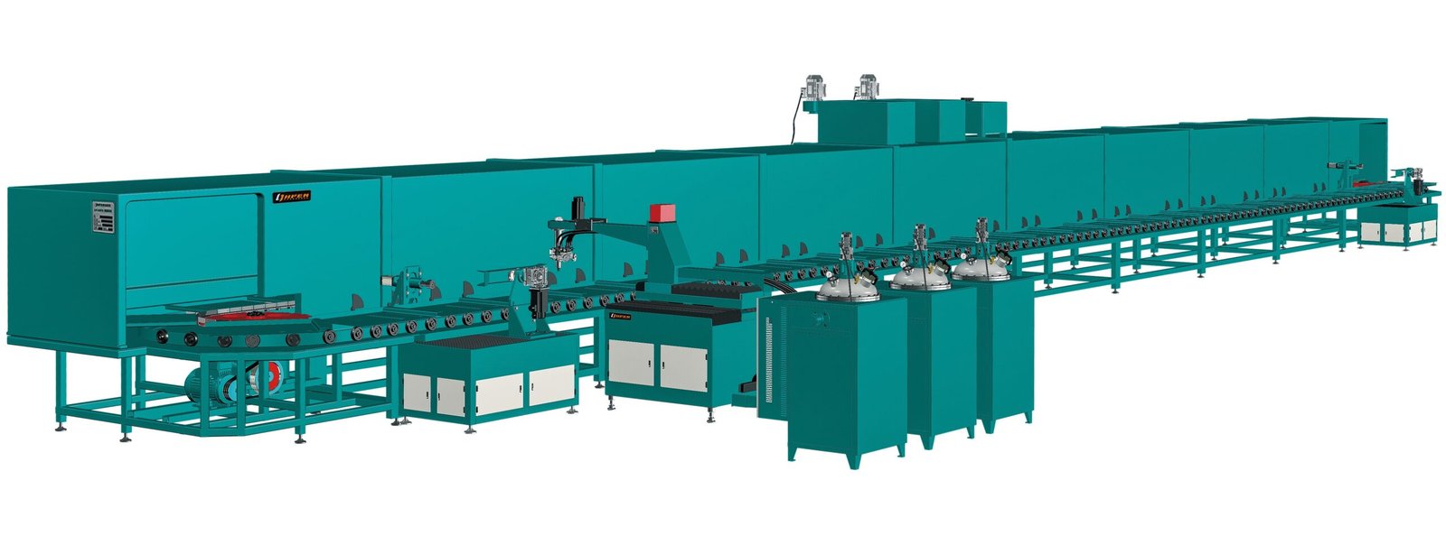
Flow marks that track the pour path often come from discharge or ratio instability. On equipment with servo or gear-pump metering, ratio deviation of more than ±0.3% may be enough to produce visible inconsistency in sensitive cast parts.
Check the mixing head speed, wear, and bubble formation. A worn rotor or chipped mixing element will not create the shear needed for homogeneous mixing, and the resulting unmixed streaks can look identical to flow marks.
When the part is a solid elastomer or a defect-sensitive microcellular part, verify that vacuum degassing is reaching at least -0.095 MPa. If the machine has automatic circulation and air-purge cleaning, confirm the circuit is not pulling air back into the material path.
Pour Pattern and Fill
Do not use the first few grams of every shot to fill a visible area. The first material out of the mix head may be partially reacted, poorly mixed, or colder than the main stream. Divert that initial material and begin the pour into the mold only when the flow is steady.
For larger or complex cavities, avoid multiple stop-start motions. Pour continuously from a low position, preferably into a runner or bottom edge, so the liquid rises uniformly instead of cascading over itself. If knit lines remain at the last point of fill, reconsider gate location or add a flow leader to move the final knit line to a non-appearance area.
Venting and Mold Release
Wipe excess mold release from the cavity. Excess release agent can be carried by the flow front and deposited as a visible band or streak. Clean vents before each shift; a vent that is partially blocked changes the filling pattern and can force air through a surface area that is visible on the part.
Cure and Demold
Do not demold the part the moment it feels solid. A short dwell time can freeze residual flow and shrinkage at the surface. Allow the part to develop sufficient green strength before handling, and keep the mold closed for the full gel-to-demold cycle specified by the material supplier.
If the mark remains as a raised line after demolding, differential shrinkage rather than short fill is often involved. Causes Of Shrinkage In Polyurethane Foam How To Control It covers the thermal and formulation drivers behind surface distortion.
Plant-Floor Verification Sequence
Run this sequence before changing the formulation or the machine program:
- Record the exact location, direction, and depth of the mark on a labeled part print.
- Weigh a full part and compare it with the designed shot weight for that cavity.
- Check the A/B ratio and discharge rate against the machine log.
- Measure material temperature at the day tank outlet and at the mix head.
- Purge or air-blow clean the mix head and inspect the rotor and chamber.
- Clean vents and remove excess mold release from the cavity.
- Raise mold temperature in small, documented steps and run a short trial.
- Log gel time, rise time, demold time, and peak exotherm for the trial.
When the verification sequence is followed, flow marks usually resolve in one of three places: short fill, premature cure, or thermal imbalance at the mold face.
Talk to Haifeng Polyurethane Machinery
If you have already adjusted shot weight, mold temperature, and pour pattern and the flow marks still return on multi-cavity lines, the problem is often equipment-level: a worn mixing head, metering drift, or a temperature-control loop that cannot hold the process window.
Send us the part drawing, material system, current mold temperature, actual shot weight, and a photo of the defect location. Our engineers can help trace whether the mark is coming from fill, cure, or equipment output consistency.
Email: Info@chinahaifeng.com
WhatsApp: 86 13566296633
Frequently Asked Questions
How much can I safely raise the mold temperature?
Raise it in 5°C steps and stay within the range given on the material TDS. If you must exceed the supplier’s upper limit to remove the marks, the fill time, gel time, or shot size is likely the real problem.
Why do flow marks appear in only one cavity of a multi-cavity mold?
Usually that cavity has a temperature, venting, or fill-path difference. Check the mold face temperature, blocked vent, gate size, and actual fill weight for that cavity specifically.
Can moisture cause flow marks?
Yes. Moisture reacts with isocyanate to release carbon dioxide and can disturb the reacting front. It may appear as a cloudy band or a rougher area around the flow mark rather than a clean hairline.
Do flow marks affect mechanical strength?
Visible surface knit lines can create a local weakness, especially in flexural or dynamic applications. If the mark can be felt as a notch or ridge, it is worth treating as a process defect rather than only a cosmetic issue.
What should I check first if flow marks are intermittent?
Start with mixing-head condition, shot-rate stability, and material temperature. Intermittent marks on an otherwise stable line are often caused by air fluctuation, worn mixing elements, or a temperature controller that cycles outside its band.
References
[1] C. Hepburn, Polyurethane Elastomers, 2nd ed., London: Elsevier Applied Science, 1992.
[2] M. Szycher, Szycher’s Handbook of Polyurethanes, 2nd ed., Boca Raton: CRC Press, 2012.
[3] ASTM D955-08, Standard Test Method of Measuring Shrinkage from Mold Dimensions of Thermoplastics, West Conshohocken: ASTM International, 2008.
If you’re interested, check out these related articles:
RRIM Vs RIM Which Process Suits Your Structural Part
Measuring Polyurethane Foam Resilience A Practical Test Guide
Shore A Vs Shore D Hardness In Polyurethane
The Role Of Rise Time In Polyurethane Foaming