

The lab reports 52 kg/m³ on the free-rise cup. Meanwhile, the same system in a closed sole mold routinely comes out at 58 kg/m³ to 61 kg/m³. Neither number is wrong. They are measuring two different things, and treating them as interchangeable is how production managers end up with short shots, overweight parts, or a density window that only exists on paper.
Density in polyurethane foam is always mass divided by volume, but the test conditions determine what that volume contains. Free-rise density describes foam that rises without a confining wall, while molded density describes the finished part. Understanding the gap between them is the first step toward setting fill weight by calculation instead of guesswork.
What Free-Rise Density and Molded Density Actually Measure
Free-rise density is the density of a foam sample produced in an open container deep enough that the rising front never touches a wall. The standard measurement principle is defined in ISO 845: the sample is conditioned, its linear dimensions are measured, mass is measured, and apparent density is calculated from mass over volume [1]. Confinement is removed from the experiment, which makes free-rise density a repeatable way to compare one liquid system against another.

In a free-rise test the mixed reactants expand against atmospheric pressure until the gel network stabilizes cell pressure. The result reflects formulation behavior: water content, catalyst balance, surfactant efficiency, polyol structure, and isocyanate index. It does not reflect what happens inside a production tool, because the tool removes open expansion.
Confinement is the difference. The Role Of Rise Time In Polyurethane Foaming covers how the rise profile changes once back pressure and cavity geometry enter the picture.
Molded density is the density of foam removed from a fixed-volume cavity at net shape. The same shot mass now has less available space, so the apparent density of the part rises. In flexible molded foam, the molded value is usually treated as the specification number because it controls part mass, hardness consistency, and material cost.
The gap between the two values is called overpack. As a ratio, overpack is molded density divided by free-rise density. In many flexible molded systems, a working range is roughly 1.1 to 1.3, but the usable number depends on venting, mold temperature, part thickness, and how much pressure the seal retains [2]. Rigid structural parts can behave differently because fill patterns and cavity pressure control are different [5].
Two Numbers, Two Jobs: A Practical Comparison
| Evaluation point | Free-rise density | Molded density |
|---|---|---|
| Where it is measured | Open cup or free-rise container | Finished core sample from a fixed cavity |
| Reference method | ISO 845 apparent-density principle [1] | ASTM D3574 for flexible cellular materials [2] |
| What it represents | Formulation and reaction behavior | Part mass over net cavity volume |
| Typical relationship in flexible foam | Baseline value | Usually higher when same shot is confined |
| What moves it | Catalyst, water, surfactant, index, material temperature | Venting, mold fill, shot weight, seal, tool temperature |
| Main production value | Incoming-system QC and lot comparison | Part specification, cost control, fill-weight calculation |
The two values are strongest when measured together on the same batch. A free-rise number alone cannot tell you what the mold will deliver in practice, and a molded number alone cannot tell you whether the raw material lot shifted.
Calculating Fill Weight From Molded Density
The correct fill weight for a closed mold is shot weight, not a vague “fill the cavity” instruction. The base calculation is:
Shot weight per part = net part volume × target molded density, plus allowances for sprue, runner, mixing-head residue, and trimmed flash.
The arithmetic stops working when the density input is wrong. How To Calculate Shot Weight In Polyurethane covers the formula with practical corrections for runners, inserts, and multi-cavity molds.
A worked example makes the point. A flat pad molds at 200 mm × 180 mm × 20 mm net, which is 0.72 liters. With a target molded density of 60 kg/m³, the net shot is:
0.72 L × 0.060 kg/L = 0.0432 kg, or 43.2 g
That is before flash and runner allowance. If the same processor instead starts from a free-rise density of 50 kg/m³ and forgets the overpack difference, the calculated shot is 36 g. The mold runs short, or the operator compensates by hand, and part-to-part density wanders.
Insert your fill correction where it belongs: additives and inserts displace foam, so their volume must be subtracted from the shot calculation. Thick-section parts may also need a small safety increment to prevent sink and voids after gel.

Five Variables That Shift the Free-Rise-to-Molded Gap
Free-rise density can hold steady while molded density drifts, which tells you the change is happening at the tool, not in the liquid system. The five variables below cause most of that drift.
Venting and cavity back pressure. A restricted vent raises cavity pressure, collapses some cells, and packs more mass into the same volume. The result is higher molded density with no change in the cup.
Mold temperature. A hotter mold lowers mixture viscosity and changes skin thickness and fill speed. Density can shift even when free-rise is stable, so a cold-start part and a steady-state part may not match until the tool reaches equilibrium.
Material and day-tank temperature. Cold material slows creaming and rise, which alters cell growth before the mold seals. This is one of the most common seasonal causes of density drift: same recipe, different part mass.
Mixing and metering quality. Poor mixing does not produce one density value; it produces a distribution. Soft spots, dense skins, and gradients across a single part often trace back to mixing-head condition or metering ratio deviation.
Water content and reaction water release. In water-blown systems, the blowing gas comes from the isocyanate–water reaction [4]. Any change in effective water level changes both free-rise density and the cell structure the mold sees [5].
This gap is rarely caused by one factor alone. Causes Of Shrinkage In Polyurethane Foam How To Control It explains how venting, temperature, and reaction imbalance interact when cells lose pressure after demold.
Quick diagnostic pattern
| Observation | Likely direction to inspect |
|---|---|
| Free-rise stable, molded density rising | Vent, seal, shot weight, mold temperature |
| Free-rise and molded density moving together | Raw material lot, material temperature, ratio |
| Values moving in opposite directions | Mixing quality, catalyst balance, water content |
| Part-to-part spread increasing | Metering accuracy, mixing head wear |

Setting a Density Window That Survives Production
A workable density window is built from paired data: on the reference part, record free-rise density, molded density, shot weight, and the overpack ratio at the same time. Free-rise becomes the early warning signal; molded density remains the specification.
A lean routine for stable production:
- Condition samples the same way before measurement, following the same preparation principle in ISO 845 [1].
- Cut core samples from the same location in the part every time, then measure by ASTM D3574 [2].
- Do not change shot weight while evaluating density shift; changing both at once makes the data unreadable.
- Track the overpack ratio instead of memorizing a universal correction factor.
If free-rise density is stable but molded density is climbing, inspect vent condition, mold seal wear, and shot weight first. If both values move together, check the material lot and day-tank temperature before touching the mold.
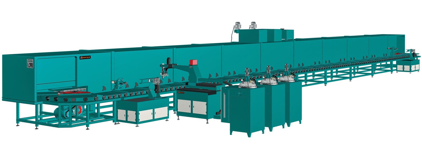
For a low-pressure dual-density insole line, this routine plays out in a concrete way: the operator pours a standard cup for free-rise density, weighs trimmed parts for molded density, and keeps the two records on one control chart. A machine with repeatable metering makes that comparison meaningful; if shot weight itself varies by several grams, density and shot-weight error become impossible to separate. On such lines we typically work with closed-loop dosing and stored formulas so the corrective action lands on the material or tool rather than on operator judgment.
Equipment Perspective: Make Fill Weight Repeatable
Fill weight is a calculated instruction, but it only becomes a process when the metering system delivers the same shot every cycle. No molding formula can fix shot-to-shot variation from a worn pump or a drifting ratio.
The practical questions to ask for this measurement are simple. Can the pour unit hold shot weight within a repeatable tolerance? Can it store the paired free-rise and molded density settings for each formula? Can the operator switch between single-density and dual-density recipes without re-trimming the shot by hand?
Density and hardness are connected, but they are not the same setpoint. The Relationship Between Density And Hardness In Polyurethane is useful when a buyer tries to raise hardness by increasing density alone and discovers the part only gets heavier.
When the firing sequence is tied to a consistent metered shot, the specification becomes achievable: set target molded density, calculate shot weight, and confirm the free-rise value as the lot-control signal. If your current line cannot hold that sequence, begin with metering accuracy and formula management before chasing the density number itself.
FAQ
Is free-rise density always lower than molded density?
In most closed-cavity flexible foaming, yes, because the same mass is confined into a smaller available volume. The gap depends on overpack. A very open cavity with generous venting can bring the two closer together, but the molded value is still the number that controls part mass.
What is a typical free-rise to molded density ratio?
Many flexible systems operate around 1.1 to 1.3, but there is no universal factor. Venting, mold temperature, part thickness, seal condition, and shot weight all move it. Relying on a fixed rule without measuring your own overpack ratio is the fastest way to overpay for material.
Why is molded density drifting while free-rise density stays the same?
Inspect the tool side first: vent restriction, mold seal wear, shot weight drift, or mold temperature changes. When the liquid system is stable in the free-rise cup but the mold result is not, the signal usually points to cavity conditions rather than formulation.
How should I condition foam before measuring density?
Follow the preparation principle in ISO 845: dimensions and mass are measured under defined conditions so the apparent density calculation is repeatable [1]. For flexible cellular materials, ASTM D3574 is the common practice in North American and many international operations [2].
Can I calculate fill weight from free-rise density?
Only with a verified overpack factor. The safer path is to calculate shot weight from target molded density and net part volume, then use free-rise density as the incoming-lot control signal. This keeps material cost and part specification on the same page.
Let’s Talk About Your Density Window
If your free-rise cups look stable but molded parts keep drifting overweight or short, we can help you structure the measurement and find where the process is moving. Describe your current part, cavity count, and shot-weight variation, and we will work through the density window and metering requirements together.
Email: Info@chinahaifeng.com
WhatsApp: 86 13566296633
References
[1] ISO 845:2006, Cellular plastics and rubbers — Determination of apparent density. International Organization for Standardization.
[2] ASTM D3574-17, Standard Test Methods for Flexible Cellular Materials — Slab, Bonded, and Molded Urethane Foams. ASTM International.
[3] Polyurethane Foam Association, Information on flexible polyurethane foam properties and density. PFA Technical Information.
[4] D. Randall and S. Lee, The Polyurethanes Book. Wiley, 2002.
[5] B. Wilson, “Water-blown flexible foam,” in Polyurethane Handbook, G. Oertel, Ed. Hanser Publishers.
If you’re interested, check out these related articles:
SRIM Explained Structural Reaction Injection Molding Basics
Measuring Polyurethane Foam Resilience A Practical Test Guide
Causes Of Shrinkage In Polyurethane Foam How To Control It