

Dual-hardness seat foaming usually fails at the boundary between the soft center and the firm bolster, not in the middle of either zone. A cushion can pass an indentation check at the center of both zones and still show a read-through line where the two foams meet, or a bolster that goes soft 20 mm in from the edge. Both are zoning and timing symptoms. The zone map decides where the hardness step belongs, the pour sequence decides whether the second shot bonds to the first, and only then does the machine specification mean anything. Reverse that order and a well-metered line still sends cushions to the trimming bench.
Why the hardness step fails at the boundary
Three things can happen when the second shot lands on the first, and only one of them is acceptable.
If the first shot is still liquid, the incoming stream pushes it across the cavity. The two formulations mix in a band whose width depends on flow speed and on the viscosity difference between them. That band cures at a hardness somewhere between the two targets, with a different cell structure, and it moves whenever the pour path or the shot weight changes. Nothing on the drawing describes it.
If the first shot has creamed and begun to rise but has not gelled, its surface still carries reactive groups. The second shot wets it, both zones rise together at the boundary, and the result is one continuous foam with a hardness step and no seam. This is the window to aim for, and it is narrow.
If the first shot has cured, the second can only key into the surface. The joint survives handling and separates during durability cycling, and because the two zones shrink by different amounts as they cool, the boundary reads as a line under thin trim.
Why the two formulations rarely react at the same speed
Hardness in molded high-resilience foam comes from density, crosslink density and the urea content produced by the water and isocyanate reaction. Firming the bolster by raising the isocyanate index or the polyol functionality also makes that side react faster. Adding water raises hardness through urea and raises gas output at the same time, which pulls density down. So the firm zone and the soft zone rarely share a cream time, and the gap widens as the hardness difference widens.
The pour window is therefore set by the formulation pair, not by a fixed number a machine supplier can guarantee. Measure cream and gel time on both sides of the proposed pair, then decide whether catalyst balance can bring the two close enough for a single-cavity, two-shot process. A metering unit can hold an interval to a fraction of a second. It cannot make two formulations agree.
The interval between two shots is only as repeatable as the rise behaviour of each formulation, because a drift in rise time moves the boundary even when the metering ratio holds. <The Role Of Rise Time In Polyurethane Foaming> covers how rise time is measured and what shifts it.
The release agent habit that breaks the bond
Operators trained on single-hardness molds spray release agent whenever the cavity looks dry. In a two-shot process, release agent sprayed between the first and second shot sits on exactly the surface that has to bond. The part demolds cleanly, passes a visual check, and separates at the boundary later. The process sheet has to state when release agent is applied, and the answer is before the first shot only, or the release agent is replaced by an in-mold coating compatible with both formulations.
Fixing the zone map before the machine
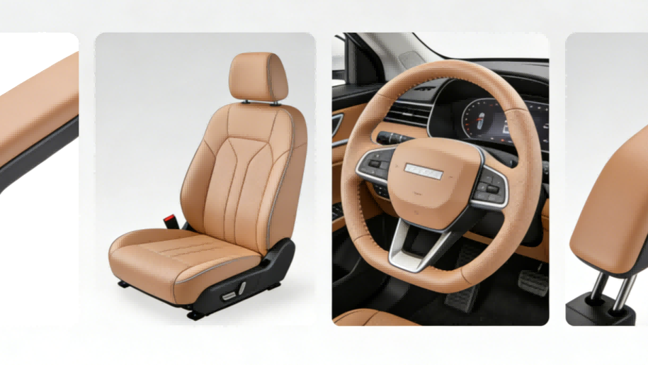
A drawing that says soft center and firm bolster is not a specification. Three quantities per zone make it one: the hardness basis, the density, and the location and width of the boundary.
Hardness basis means an indentation force at two indentation levels on a defined pad geometry, plus the sag factor, which is the ratio of the 65% value to the 25% value. A durometer reading on flexible seat foam is not a substitute. The sag factor also tells the moulder whether the two zones will feel different under a seated load or only in the lab, because two foams can share the same 25% value and behave quite differently at 65%.
Density is the second decision. If the firm zone also needs higher density to reach its hardness, the part gains weight and the two zones shrink by different amounts on cooling. That difference is what telegraphs through leather. If the bolster hardness can be reached through index and crosslinker at matched density, the boundary is far easier to keep invisible.
The boundary itself needs a position on the drawing with a tolerance, not a description in words. Pour points are placed to serve that line, venting is placed around it, and the trimming allowance is set from it.
| Element | What to put on the drawing | Why the moulder needs it | What goes wrong without it |
|---|---|---|---|
| Center zone | 25% and 65% indentation force, sag factor, density, thickness tolerance | Sets the formulation and the shot weight | Center measures in range but feels hard after twenty minutes |
| Bolster | Same basis plus a compression set limit | Sets index and crosslinker, and the cure time that governs demold | Bolster softens at the edge nearest the boundary |
| Boundary | Position with tolerance, permitted mixed band width, bond test method | Decides pour points, vents and divider position | Mixed band moves with the pour path and shows under trim |
| Trim interface | Permitted sink or read-through under the actual cover | Decides whether the two densities must be matched | Line appears only after the seat is upholstered |
Three routes to two hardness zones in one seat
Route choice is the decision that fixes machine count, floor space and labor, so it belongs before the equipment quotation, not after it.
| Route | How the step is made | Fits when | Do not choose it when |
|---|---|---|---|
| Two sequential pours, one cavity | Second shot lands on the first while it is still reacting | Both formulations can be trimmed to converge cream and gel, and the zone map is stable across the model range | Reactivities cannot be converged, or the pour path cannot be repeated from part to part |
| Split cavity with a removable divider | Zones pour independently, divider pulled on a set schedule | Hardness difference is large, or the two formulations need very different catalyst packages | The trim cannot hide a seam, or the divider would mark a visible skin |
| Pre-formed insert in a single pour | A firmer pad is located in the bolster before one shot | One metering system is enough, volumes are low, or designs change often | Insert placement time exceeds the takt, or the insert shifts under the pour |
A single-cavity two-shot process needs two polyol lines against one isocyanate, plus either two pour stations or one station with a dwell. A split-cavity process can run on two independent machines feeding one line, which is sometimes cheaper than a two-polyol metering unit when a plant already owns a spare machine. The insert route needs one stream and more labor. Routes can be mixed across a seat set, with the cushion on one and the backrest on another, but not within one cavity.
What the metering system must do when the recipe changes mid-cycle
The architecture follows the chemistry. If both zones share the same isocyanate and differ only in polyol, water, catalyst and crosslinker, one isocyanate line and two polyol lines will do. If the isocyanates differ, for instance a TDI-based system against an MDI-based one, the cell needs two complete component sets or two machines, because blending isocyanates in one manifold invites ratio error and gelling at the head.
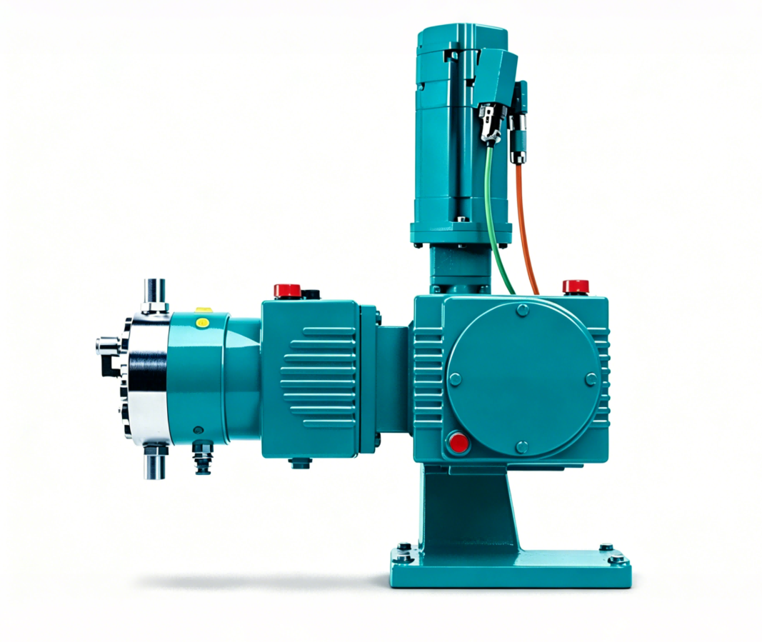
The HF-HPM-1A1B-CarSeat head covers 50 to 1000 g/s, holds a polyether to isocyanate ratio of 100:45 to 60, and meters within ±0.3% across the range, with 100 L and 150 L tanks and 10 to 18 MPa mixing pressure. Those figures matter in three ways for a dual-hardness cell. The pour rate has to cover the larger of the two shots inside the takt. The ±0.3% figure is effectively the hardness tolerance, because index drift moves hardness and cure speed together. And tank size must be set on consumption split rather than total shot weight, since a bolster polyol that accounts for a third of the shot drains at a third of the rate and needs its own changeover schedule.
Calculate shot weight per zone rather than per part, then check both numbers every cycle.
Shot weight errors show up as density drift long before they show up as scrap, and two shots per cycle give you two chances to drift. <How To Calculate Shot Weight In Polyurethane> covers how the volume, density and loss terms are put together.
Every switch between polyols at the head needs a purge, and every purge is material loss plus time inside the takt. Count it in the cycle before you promise an output figure.
Mold, divider and pour point layout
Pour points should be placed so each zone’s flow front arrives at the boundary at the end of fill, and so the second shot never has to travel across the first zone. A front that reaches the boundary late leaves that surface fresh and reactive when the second shot lands. A front that arrives early leaves a cooled, coarser free-rise skin on exactly the line that needs to bond.
Vent each zone at its high point and vent the boundary as well. Gas trapped along the boundary becomes a void band, which reads as a soft strip and fails a cross-section check even when the indentation values are correct.
The divider, where one is used, should be thin, drafted, and located where the trim can cover it. Pull it before the first zone gels if a chemical bond across the line is required, or after demold if a mechanical seam is acceptable. Record the pull time on the process sheet, because it drifts when the line gets busy.
Hold both zones at the same mold setpoint within the tolerance the trial establishes. A temperature difference between zones changes cream and gel locally and moves the boundary with no change to the recipe at all, so check temperature at the mold face rather than at the heater controller.
Locate any insert with pins or pockets rather than operator judgement. An insert that shifts 5 mm under the pour produces a bolster that is firm on one part and soft on the next, with no metering fault to find.

Line layout for a two shot cycle
On a rotary carousel the interval between pours is a multiple of the index time plus any dwell. That turns the geometry of the line into a process constraint, and it is the part most often missed at the quotation stage.
| Interval the formulation pair needs | Pour head layout | Effect on the carrier |
|---|---|---|
| Less than one index time | Both heads at one station, second pour on a dwell | Carrier waits; takt becomes both pours plus the dwell |
| About one index time | Heads one station apart | No dwell, interval fixed by the machine index |
| About two index times | Heads two stations apart | No dwell, but the first zone cures further than a clean bond may tolerate |
If the trial says the pair needs 130 seconds and the index is 94 seconds, the carousel offers 94 or 188 and neither is right. The pair then has to be trimmed to fit an achievable interval, or the index time has to change.
A seat project delivered by Haifeng Polyurethane Machinery in Changzhou shows how the arithmetic behaves. Sixteen-station rotary carriers on three lines, running at 25 minutes per cycle, produced about 550 seat sets a day over two shifts, which works out to roughly a 94 second takt, while the defect rate fell from 11% to 1.5% after metering and carrier changes. Add a second pour and that cycle grows by the interval unless the interval hides inside the index, and the station count grows with it.
Those figures describe what a metering and carrier change achieved on a single-formulation seat line. They do not predict what a dual-hardness conversion will deliver, because the interface yield and the extra station are new variables that only a trial on the actual mold can settle.
Checks before releasing a dual-hardness seat to production
- Peel the boundary at three locations. The failure must be a foam tear, not a clean separation. A clean pull means the second shot keyed instead of bonding.
- Cut cross-sections at the center, the boundary and the bolster. Measure the mixed band width and count voids against the limit on the drawing.
- Run indentation force at 25% and 65% in each zone center and at the boundary, then calculate the sag factor per zone.
- Weigh every part in the first twenty and compare against the calculated shot weight for each zone.
- Apply a static load or compression set check at the boundary, since that is where the two cell structures meet.
- Check the demolded part under the actual trim, not bare foam, because a read-through line appears only after upholstery.
- Record the pour interval, ratio actuals, mold temperature and both shot weights for the first twenty parts, so a later drift can be traced to one variable.
Comfort checks and bond checks answer different questions, and a seat can pass one while failing the other. <Measuring Polyurethane Foam Resilience A Practical Test Guide> covers how resilience is measured and what the result does and does not tell you about a finished seat.
What to send for a layout review
Send the zone map with the boundary position and tolerance, the hardness basis and density for each zone, your preferred route, the required interval if the trials have produced one, takt time and shift pattern, cavity count and mold footprint, available floor length, and the metering assets you already own. With those, the station count and the pour head spacing can be worked out before any quotation, and the formulation pair can be checked against the interval the line can actually deliver.
Haifeng Polyurethane Machinery, Info@chinahaifeng.com, WhatsApp 86 13566296633.
FAQ
Can one foaming machine produce both hardness zones?
Yes, when both zones share the same isocyanate and differ only in the polyol side, which is the common case for molded high-resilience seat foam. The machine needs one isocyanate line, two polyol lines and a head that can switch and purge between them. If the two zones require different isocyanates, for example a TDI system against an MDI system, one machine with two full component sets is needed, or two separate machines feeding the same line. Confirm the isocyanate question before comparing quotations, because it changes the machine count.
How much harder can the bolster be than the center?
There is no universal ratio, because the limit comes from the reactivity gap rather than from hardness alone. The further the bolster formulation is pushed on index or crosslinker, the faster it reacts, and the harder it becomes to land the second shot inside the bonding window. If the pair can be brought close in cream and gel time, a substantial step is achievable in one cavity. If the gap stays wide, a split cavity or a pre-formed insert is the more reliable route.
Does dual-hardness change the demold time?
Usually yes, because the cycle is set by the slower of the two zones rather than by the average. A firm bolster with a high index may cure quickly while the soft center, with more water and a lower crosslink density, needs longer before it can be handled without tearing. The interval between shots also consumes cycle time unless it is absorbed by the carrier index. Measure both zones separately, then set demold on the slower one.
Why does the boundary line show through the leather?
Two mechanisms, often together. The first is a density step, which makes the firmer zone shrink less than the softer one as the part cools, leaving a small ridge along the boundary. The second is a mixed band of intermediate hardness that cures at a different rate and pulls differently from both zones. Matching densities reduces the first. Placing the boundary under a seam or a bolster crease hides what remains, and that placement is a design decision, not a molding one.
If you’re interested, check out these related articles:
The Role Of Rise Time In Polyurethane Foaming
How To Calculate Shot Weight In Polyurethane
Measuring Polyurethane Foam Resilience A Practical Test Guide
How Polyurethane Rollers Are Made From Casting To Cure