
Cyclopentane High-Pressure PU Foaming Machine | Rigid Insulation Foam
Cyclopentane high-pressure PU metering and impingement mixing with 150–500 g/s combined output at 1:1, twin 280 L tanks and PLC-controlled circulation.
150–500 g/s
Combined output at a 1:1 component ratio
10–20 MPa
Adjustable injection pressure
2 × 280 L
Independent component tanks
Two-Component High-Pressure Processing
Cyclopentane high-pressure PU metering and impingement mixing with 150–500 g/s combined output at 1:1, twin 280 L tanks and PLC-controlled circulation.
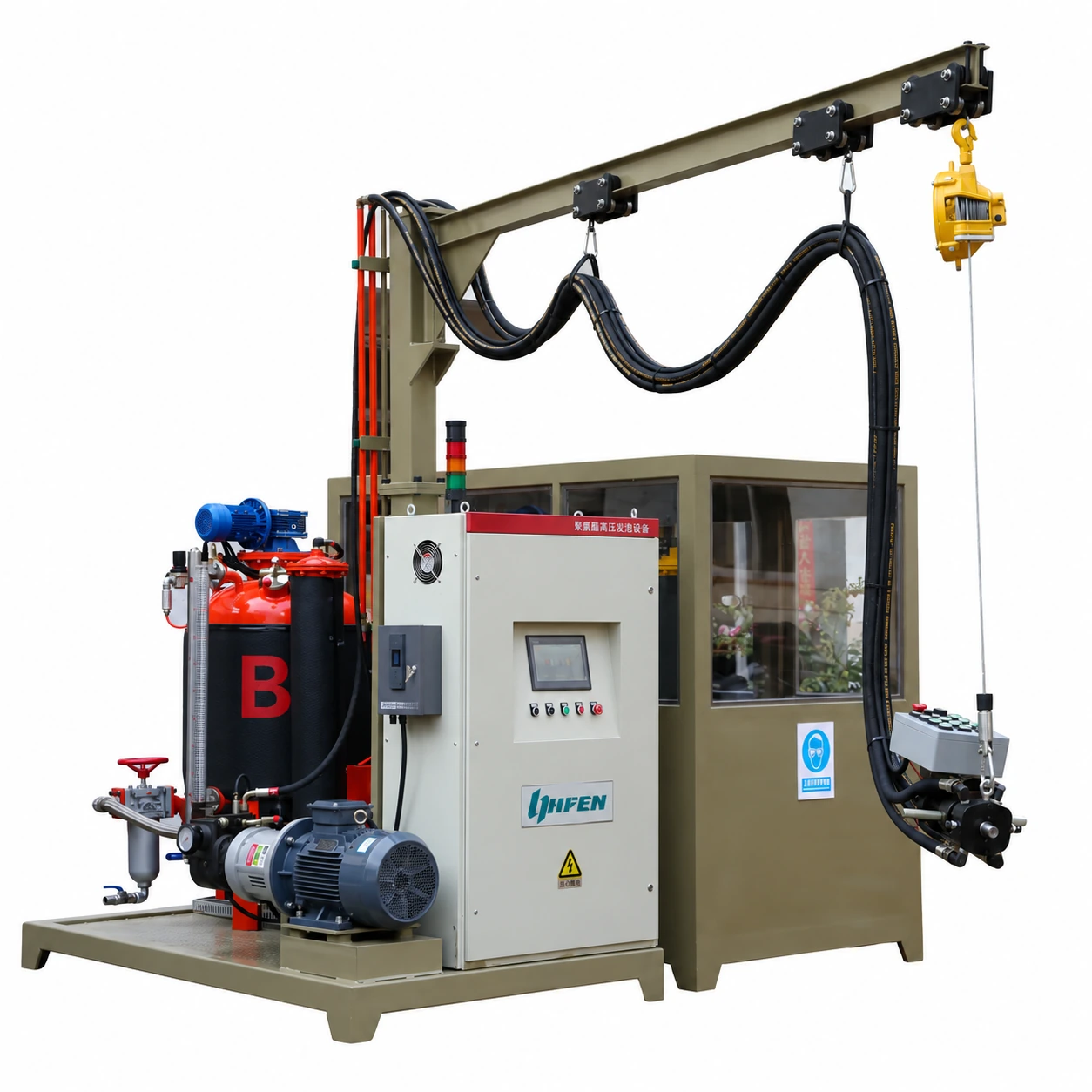
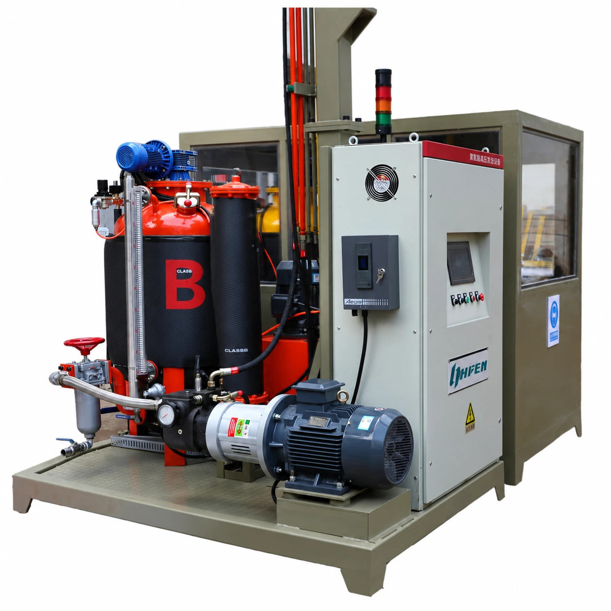
Haifeng supplies this two-component high-pressure PU foaming configuration for cyclopentane-based material processing. Independent polyol and isocyanate metering circuits feed a hydraulically operated, mechanically self-cleaning impingement mixing head. The equipment package includes material tanks, metering pumps, a hydraulic unit, component circulation, temperature conditioning and PLC/HMI controls.
The JHG-AFL-30 configuration specifies a combined injection output of 150–500 g/s at a 1:1 component ratio, equivalent to 9–30 kg/min. Injection pressure is adjustable from 10 to 20 MPa, and the stated component ratio range is 1:2–2:1. Final sizing uses the selected formulation, shot weight and cycle requirements.
A gas-detection unit, audible alarm and extraction interface are included in the technical scope. Detector settings, ventilation requirements, interlock actions and applicable component documentation are defined with the final project configuration.
Material Flow and Injection Cycle
Condition and circulate
Refill the tanks, establish material circulation and set component temperatures for the selected formulation.
Verify component delivery
Test the component discharge at the mixing head and calibrate flow, ratio and shot duration.
Mix and inject
Switch the component circuits to injection, impingement-mix the streams and complete the mechanical head-cleanout cycle.
Technical Parameters and Plant Interfaces
Reference configuration from the supplied technical agreement. Output is stated at a 1:1 ratio; final component selection and interface settings are confirmed for the project.
| Technical Parameter | JHG-AFL-30 |
|---|---|
| Components | 2 components: polyol mixture and isocyanate |
| Output Range (g/s) | 150–500 g/s combined output at 1:1; equivalent to 9–30 kg/min |
| Mixing Ratio Range | 1:2–2:1 adjustable; confirm component order and calibration for the formulation |
| Ratio Accuracy | Not specified as a separate ratio-accuracy value; verify component discharge during calibration |
| Power Supply | 380 V, 50 Hz; approximately 28 kW total power in the reference configuration |
| Working Pressure | 10–20 MPa adjustable injection pressure |
| Tank Capacity (L) | 2 × 280 L component tanks |
| Weight | Approximately 1.5 t, reference configuration |
| Dimensions (L×W×H) | 3.8 × 3.0 m reference footprint; height and head clearance to be confirmed |
| Injection timer | 0.01–99.99 s stated setting range |
| Shot repeatability | ≤±1% for injection duration greater than 1 s |
| Metering pumps | Two A2VK-12 high-pressure metering pumps |
| Pump drives | 7.5 kW metering-pump drives; variable-frequency control and magnetic couplings |
| Mixing-head type | JHL-1410; hydraulically operated, mechanically self-cleaning impingement head |
| Hydraulic circuit | 10 L/min flow; 16–20 MPa stated system-pressure range |
| Hydraulic reservoir and accumulator | 80 L reservoir; 10 L accumulator |
| Material temperature conditioning | 22°C stated summer control point, ±2°C deviation; recipe setpoint agreed with material supplier |
| Temperature-control unit | 5 HP heating/cooling unit with two return-circuit heat exchangers |
| Compressed air | Dry, oil-free air; reference pressure 0.7 MPa and consumption 600 NL/min |
| Control hardware | Siemens PLC and 10-inch touchscreen HMI |
| Material refill | Two pneumatic diaphragm refill pumps; level indication with limit protection |
| Component filtration | 100 μm slit/scraper filters in the component circuits |
| Gas monitoring interface | Gas detector, audible alarm and linked extraction interface; settings agreed in the project scope |
| Tank pressure schedule | POL and ISO tank working-pressure limits, design pressures and relief-valve setpoints are specified separately in the approved vessel design and nameplate documentation, in accordance with the applicable pressure-vessel code |
Metering, Mixing and Control Functions
Independent High-Pressure Metering
A2VK-series component pumps, variable-frequency drives and magnetic couplings supply the polyol and isocyanate circuits.
Mechanical Mixing-Head Cleanout
The JHL-1410 hydraulic mixing head uses high-pressure impingement and mechanical cleanout. A balancer supports manual head-height adjustment.
High- and Low-Pressure Circulation
Coordinated circuit changeover controls material circulation and injection. Component discharge can be checked at the head.
Material Temperature Conditioning
Independent temperature sensors and return-line heat exchangers coordinate with the heating/cooling unit.
PLC and Touchscreen Operation
The HMI displays shot weight, component ratio, material levels, high/low component pressures and equipment alarms.
Monitoring and Extraction Interfaces
The supplied scope includes gas detection, an audible alarm and extraction actuation. Pressure and level monitoring support the defined equipment sequence.


