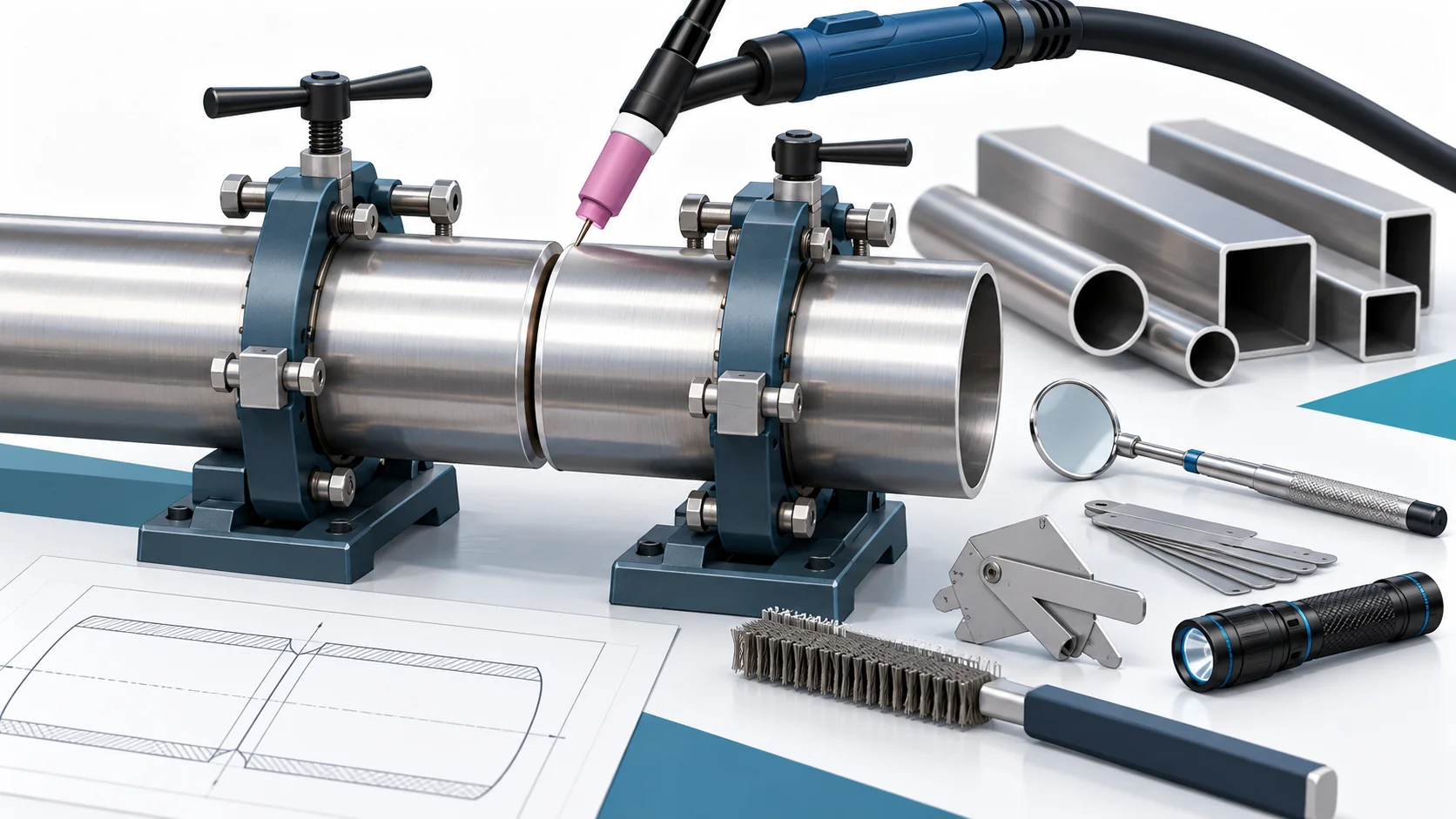
Haifeng Process Standards: Quick Reference
Welding quality in Haifeng polyurethane equipment directly affects frame rigidity and piping-seal reliability. For every 1 mm/m that frame-weld distortion exceeds the specified tolerance, the servo metering-pump mounting datum can shift by more than 0.05 mm during final assembly, indirectly affecting metering-ratio accuracy. Piping welds must pass a 0.02 MPa air-tightness test with no leakage.
Quick reference for key process parameters:
| Parameter | Haifeng Standard | Industry Reference | Related Equipment Accuracy |
| Transverse shrinkage per butt weld on frame square tube | 0.50–0.60 mm per weld (0.5 mm process allowance) | Estimated by experience | Servo installation-datum deviation after final assembly ≤0.5 mm |
| Longitudinal shrinkage rate of frame welds | 2–3 mm/m (process allowance) | Estimated by experience | Frame straightness over full length ≤2 mm/m |
| Heat input for 316L stainless-steel piping | ≤1.5 kJ/mm | ≤2.5 kJ/mm | Weld passes intergranular-corrosion requirements |
| Welding-current stability | ±1 A adjustment accuracy | ±3 A | Penetration consistency CV ≤5% |
| Weld reinforcement (pipe butt weld) | 0–2 mm | 0–3 mm | Sealing-surface flatness ≤0.1 mm |
| Pipe misalignment | ≤10% of wall thickness and ≤0.5 mm | ≤10% of wall thickness | Smooth internal transition with no turbulence dead zones |
| Piping air-tightness test | 0.02 MPa, no leakage for 30 min | 0.02 MPa | Piping-system sealing meets requirements |
| Weld undercut depth | ≤0.5 mm; continuous length ≤100 mm | ≤0.5 mm | Fatigue life of pressure welds is maintained |
| Pre-weld cleaning area for stainless steel | ≥50 mm on both sides of bevel | ≥30 mm | Porosity ≤0.5% |
| Interpass temperature for 316L | ≤150°C | ≤200°C | Avoids extended dwell in the sensitization range |
| Tungsten-electrode tip angle | 15°–30° (sharp cone) | 30°–60° | Concentrates arc heat and reduces HAZ width |
| Frame straightness after welding | ≤1‰ of full length and ≤3 mm | ≤2 mm/m | Meets JB/T 11509 manufacturing-accuracy requirements |
1. Scope
1.1 Application
This SOP applies to the following welding operations for Haifeng polyurethane equipment:
| Welded Component | Typical Material | Welding Method | Quality Level |
| Square-tube frame | Q235B / Q345B | GMAW (MAG) | ISO 5817 Level C |
| Stainless-steel material tanks and heads | 304 / 316L | GTAW root pass + GMAW cap pass | ISO 5817 Level B |
| Isocyanate / polyol feed piping | 316L | All-position GTAW | ISO 5817 Level B |
| High-pressure mixing-head piping | 316L / 17-4PH | GTAW | ISO 5817 Level B |
| Temperature-control jacket piping | 304 | GTAW | ISO 5817 Level C |
2. Pre-Work Preparation and Welding-Procedure Qualification
2.1 Welding-Procedure Qualification (WPQR) and WPS
All Haifeng welding work must follow a Welding Procedure Specification (WPS) qualified to ISO 15614-1. The WPS must include the following essential variables:
| No. | WPS Variable | Haifeng Requirement |
| 1 | Parent-material group | Classified according to ISO/TR 15608 (e.g., Group 1.1 carbon steel, Group 8.1 austenitic stainless steel) |
| 2 | Welding process | GTAW (141) / GMAW (135); specify whether pulsed |
| 3 | Welding position | Specify according to ISO 6947 (PA/PF/PC, etc.) |
| 4 | Joint design | Bevel type and angle, root face, fit-up gap and tolerances |
| 5 | Filler metal | Specify classification, size and batch; for 316L piping, prefer ER316L filler wire (Mo content ≥2.0%) |
| 6 | Electrical parameters | Current, voltage, welding speed and permitted ranges |
| 7 | Shielding gas | Type, purity (≥99.99%) and flow rate |
| 8 | Preheat / interpass temperature | Carbon steel ≥15°C; 316L interpass temperature ≤150°C |
| 9 | Heat input | Calculated value and permitted upper limit |
2.2 Welding-Equipment Accuracy Calibration
| Equipment / Tool | Accuracy Requirement | Calibration Interval |
| Welding-power-source ammeter | ±1 A adjustment accuracy | Every 3 months |
| Welding-power-source voltmeter | ±0.1 V adjustment accuracy | Every 3 months |
| Heat-input data logger | Synchronized sampling of current, voltage and speed at ≥10 Hz | Every 6 months |
| Infrared thermometer | ±1% of reading | Every 6 months |
| Weld gauge | 0.1 mm resolution | Every 6 months |
| Bevel-angle gauge | 0.5° resolution | Every 12 months |
Haifeng welding power sources must provide constant-current and constant-voltage output modes, have a power factor ≥0.95, and support preset and stored welding parameters (at least 100 sets) for rapid changeover and traceability across product models.
3. Structured Welding Workflow
3.1 Pre-Weld Preparation and Material Control
3.1.1 Parent-Material and Filler-Metal Verification
| Inspection Item | Haifeng Standard | Verification Method |
| Parent-material certificate | Matches material grade on the drawing | Verify heat/batch number |
| Filler-metal classification | Matches the WPS | Check package markings |
| Filler-metal storage | Store stainless-steel and carbon-steel filler metals in separate zones | Visual inspection |
| Filler-metal drying | Follow filler-metal manufacturer’s instructions, where applicable | Drying log |
| Shielding-gas purity | ≥99.99% (Ar) | Gas analysis certificate |
3.1.2 Bevel Preparation and Cleaning
Stainless steel is extremely sensitive to surface contamination. Grease, moisture or oxide scale left before welding can decompose in the high-temperature arc, cause porosity or reduce weld corrosion resistance.
| Step | Operation | Accuracy Standard |
| Bevel preparation | Machine or plasma-cut, then grind | Bevel-angle deviation ≤±2.5° |
| Cleaning area | At least 50 mm on each side of the bevel | Wipe with acetone or anhydrous ethanol |
| Oxide removal | Grind with a dedicated stainless-steel wire brush to bright metal | Do not use a carbon-steel brush |
| Fit-up gap | Square groove: 0–0.5 mm; V-groove: as specified in WPS | Check with feeler gauge |
| Misalignment | ≤10% of wall thickness and ≤0.5 mm | Weld gauge |
3.2 Tack Welding and Distortion Control
3.2.1 Tack-Weld Parameters
Tack welding is critical to controlling weld distortion and dimensional accuracy. Tack spacing must be 50–100 mm, tack length approximately 5–10 mm, and penetration should generally be controlled to within 0.8 mm to avoid stress concentrations during final welding.
| Welded Component | Tack Spacing | Tack Length | Penetration Control |
| Square-tube frame (3–6 mm wall) | 80–100 mm | 8–10 mm | ≤1.0 mm |
| Stainless-steel piping (2–4 mm wall) | 50–80 mm | 5–8 mm | ≤0.8 mm |
| Longitudinal seam on tank shell | 100–150 mm | 10–15 mm | ≤1.5 mm |
3.2.2 Welding-Distortion Pre-Compensation
Based on data validated by testing, Haifeng welding procedures use the following distortion pre-compensation strategy:
| Weld-Joint Type | Measured Shrinkage | Process Allowance |
| Transverse shrinkage of butt joint | 0.50–0.60 mm per weld | Allow 0.5 mm for each transverse seam |
| Longitudinal weld shrinkage | Double-sided welds shrink more than single-sided welds | Allow 2–3 mm per meter of longitudinal weld |
| Frame fillet joint | Adjust according to structural rigidity | Determine using trial-weld data |
3.3 Welding Parameters and Heat-Input Control
3.3.1 Recommended GTAW Parameters for Stainless-Steel Piping
Recommended welding parameters for 316L stainless-steel piping commonly used in Haifeng equipment:
| Pipe Wall Thickness (mm) | Tungsten Diameter (mm) | Filler-Wire Diameter (mm) | Welding Current (A) | Argon Flow (L/min) | Nozzle Diameter (mm) |
| 1.5 | 1.6 | 1.2 | 40–65 | 7–9 | 8.0 (#5) |
| 2.0 | 1.6–2.4 | 1.6–2.0 | 55–85 | 8–10 | 9.5 (#6) |
| 3.0 | 2.4 | 2.0–2.4 | 80–110 | 10–12 | 11.0 (#7) |
| 4.0 | 2.4 | 2.4 | 100–140 | 10–12 | 11.0 (#7) |
Accuracy control: Welding-current adjustment accuracy must reach ±1 A, and voltage adjustment accuracy must be ±0.1 V. During welding, current fluctuation must not exceed ±3% of the set value.
3.3.2 Heat-Input Control (Critical Accuracy Parameter)
If austenitic stainless steel remains too long in the 450–850°C sensitization range, chromium carbides can precipitate and cause intergranular corrosion. Heat input must therefore be strictly controlled when welding 316L piping in Haifeng equipment that contacts isocyanate.
| Welded Component | Haifeng Heat-Input Limit | Industry Reference | Control Measures |
| 316L piping (wall thickness ≤3 mm) | ≤1.0 kJ/mm | ≤2.5 kJ/mm | Low current, fast welding, pulsed mode |
| 316L piping (wall thickness 3–6 mm) | ≤1.5 kJ/mm | ≤2.5 kJ/mm | Multiple layers and passes; interpass cooling |
| 304 tank shell | ≤1.5 kJ/mm | ≤2.5 kJ/mm | Symmetrical welding and back-step sequence |
3.4 Weld Inspection and Sealing Verification
3.4.1 Visual Weld Inspection
| Inspection Item | Haifeng Standard (Level B Weld) | Inspection Tool |
| Weld reinforcement | 0–2 mm (pipe butt weld) | Weld gauge |
| Undercut depth | ≤0.5 mm; continuous length ≤100 mm; total undercut on both sides ≤10% of weld length | Weld gauge |
| Misalignment | ≤10% of wall thickness and ≤0.5 mm | Weld gauge |
| Surface porosity | Not permitted (Level B) | Visual inspection and 5× magnifier |
| Lack of fusion / incomplete penetration | Not permitted | Visual inspection and penetrant testing |
| Weld-width uniformity | Deviation ≤2 mm | Caliper |
3.4.2 Non-Destructive Testing
| Test Method | Application | Acceptance Level | Inspection Rate |
| Penetrant testing (PT) | Surface defects in stainless-steel piping | ISO 23277 Level 2X | 100% |
| Radiographic testing (RT) | Longitudinal and circumferential tank-shell welds | ISO 10675-1 Level B | At least 20% sampling |
| Air-tightness test | All feed piping | 0.02 MPa for 30 min | 100% |
| Hydrostatic test | Tanks and pressure piping | 1.5 times design pressure | 100% |
After welding piping joints, perform an air-tightness test at 0.02 MPa. The test passes if there is no leakage for 30 minutes. For the tightness test, reduce internal pressure to operating pressure; the test passes if there is no leakage for 30 minutes and the pressure drop does not exceed 0.02 MPa.
4. Core Welding-Accuracy Parameter Table
| No. | Accuracy Category | Parameter | Haifeng Standard | Inspection Tool | Inspection Frequency |
| 1 | Dimensional accuracy | Cut-length deviation for frame square tube | ±0.5 mm | Tape measure and square | 100% inspection |
| 2 | Dimensional accuracy | Frame diagonal deviation | ≤2 mm within a 3 m × 3 m area | Laser distance meter | 100% inspection |
| 3 | Dimensional accuracy | Frame straightness after welding | ≤1‰ of full length and ≤3 mm | Level and taut line | 100% inspection |
| 4 | Dimensional accuracy | Pipe-joint misalignment | ≤10% of wall thickness and ≤0.5 mm | Weld gauge | 100% inspection |
| 5 | Process parameter | Welding-current stability | ±1 A adjustment accuracy | Built-in power-source meter | Real-time monitoring |
| 6 | Process parameter | Heat input (316L piping) | ≤1.0 kJ/mm (wall thickness ≤3 mm) | Heat-input data logger | Record each pass |
| 7 | Process parameter | Interpass temperature (316L) | ≤150°C | Infrared thermometer | Check each pass |
| 8 | Weld quality | Weld reinforcement | 0–2 mm | Weld gauge | 100% inspection |
| 9 | Weld quality | Undercut depth | ≤0.5 mm | Weld gauge | 100% inspection |
| 10 | Weld quality | Porosity (RT) | Not permitted for Level B welds | Radiographic testing | Sampling inspection |
| 11 | Sealing performance | Piping air-tightness test | 0.02 MPa / 30 min, no leakage | Pressure gauge and leak-detection solution | 100% inspection |
5. Common Problems and Process Pitfalls
5.1 Frame-Weld Distortion Shifts Final-Assembly Datums
Symptom: After frame welding, the diagonal deviation exceeds tolerance, or final assembly reveals that the servo metering-pump mounting base is not flat. Extensive weld repair, cutting and grinding are required.
Root cause: Polyurethane foaming-machine frames have many welds and complex structures. Concentrated welding heat causes uneven shrinkage. In industry, foaming-equipment frames can have low welding accuracy, requiring local weld repair, cutting and grinding during final assembly and resulting in poor product consistency.
Solutions:
1. During cutting, allow for process shrinkage based on measured data (0.5 mm per transverse weld and 2–3 mm/m for longitudinal welds).
2. Use a symmetrical welding and back-step sequence to balance heat input.
3. After welding, check diagonals with a laser distance meter. If deviation exceeds 2 mm, investigate the cause and adjust the process.
4. Correct final-assembly datum deviation with shims. Do not use flame straightening.
5.2 Intergranular Corrosion in Stainless-Steel Pipe Welds
Symptom: Rust spots appear near pipe welds after several months, or piping passes the air-tightness test but begins leaking after a period of operation.
Root cause: If 316L stainless steel remains too long in the 450–850°C sensitization range, chromium carbides precipitate and deplete chromium at grain boundaries. Excessive heat input or uncontrolled interpass temperature is the main cause.
Solutions:
1. Strictly limit heat input to ≤1.0 kJ/mm for wall thickness ≤3 mm.
2. Use pulsed welding to reduce heat accumulation.
3. Check interpass temperature after every pass; it must be below 150°C.
4. Pickle and passivate the weld after completion to restore the surface passive film.
5.3 Poor Internal Pipe-Weld Profile Causes Material Retention
Symptom: The proportioning accuracy of isocyanate piping gradually drifts, or cleaning intervals become noticeably shorter.
Root cause: Excessive internal weld reinforcement or a concave weld profile creates dead zones where material can collect. Isocyanate may self-polymerize in these areas, gradually blocking the pipe and changing its effective flow area.
Solutions:
1. Use internal argon purging when welding piping to ensure a smooth root profile.
2. Limit internal weld reinforcement to 0–1 mm, stricter than the external-weld standard.
3. After welding critical piping, including the mixing-head inlet section, inspect the internal profile with a borescope.
4. Mechanically grind internal defects to a smooth transition and repassivate after grinding.
5.4 Insufficient Shielding Gas Causes Oxidation and Porosity
Symptom: Stainless-steel welds are black or show pronounced oxide colors, or RT reveals scattered porosity.
Root cause: Shielding-gas flow is insufficient, a gas lens is not installed, or wind interferes with the welding area during field welding. Oxidation of austenitic stainless-steel welds also reduces corrosion resistance.
Solutions:
1. Adjust gas flow according to plate thickness and nozzle diameter to protect the weld pool and heat-affected zone.
2. Install a gas lens to improve laminar shielding.
3. For field welding, set up a wind screen. Take additional protection measures when wind speed exceeds 2 m/s.
4. Pickle weld surfaces if oxidation exceeds a light-straw color.
5.5 Improper Flame Straightening Causes Secondary Damage
Symptom: Flame straightening is used after frame distortion, followed by abnormal local hardness or cracking.
Root cause: Straightening temperature is not controlled properly. For stainless steel, the flame-straightening temperature must not exceed 580°C. Use a neutral flame, hold it 3–5 mm from the workpiece and move it rapidly. Excessive temperature increases sensitization, while abrupt correction can introduce new residual stresses.
Solutions:
1. Strictly limit flame-straightening temperature for stainless steel to ≤580°C, monitored with temperature-indicating crayons.
2. Use gradual flame straightening. Avoid abrupt corrections with triangular or line heating.
3. Allow carbon-steel frames to cool naturally after flame straightening; do not water-quench.
4. After straightening, take sample hardness readings in the heated area. Hardness must not exceed 120% of the parent-material hardness.
5.6 Mixing Filler Metals Reduces Corrosion Resistance
Symptom: Carbon-steel or 304 filler metal is used instead of 316L filler metal. No obvious issue appears initially, but the weld preferentially corrodes over time.
Root cause: The difference in molybdenum content between 316L (2.0–3.0% Mo) and 304 (no Mo) results in substantially different corrosion resistance in chloride-containing and acidic environments. Corrosion requirements from isocyanate and additives make it essential to match filler-metal corrosion resistance to that of the parent material.
Solutions:
1. Maintain a filler-metal issue log. For welding 316L piping, issue ER316L wire against the WPS.
2. Before welding, use a spectrometer to sample and verify that filler-metal Mo content is ≥2.0%.
3. Store stainless-steel and carbon-steel filler metals in physically separate, clearly labeled locations.
4. Cut out and rework any weld made with unauthorized substitute filler metal.