A void is not a random flaw; it is a small record of something that went wrong before or during gel. In a cast elastomer roller it may show up only after the part is cut and a smooth-walled cavity appears near the core. In a molded sole it may fail a section test that looked fine from the outside. The common thread is that the gas, air, or contraction happened at a known point in processing, which means the root cause can usually be traced instead of guessed.
What Kind of Void Are You Looking At?
Before changing any setting, define the cavity. A true gas void generally has smooth, concave walls and no torn, stringy material around it; the material simply did not occupy that volume. A surface pinhole is the same mechanism breaking the surface. A knit or flow mark is not the same defect, because material meets but does not fuse. A shrinkage cavity forms after gel and follows a different set of causes. [1]
Correct naming matters because the responses differ. A trapped-air void often responds to venting and fill-pattern changes. A moisture-driven void responds to drying or vacuum degassing. Shrinkage in a thick-to-thin transition may respond to mold temperature, pack pressure, or formula gel time. Treating a fill-pattern void as a moisture problem keeps the defect count flat while the wrong variable gets changed.
Moisture and Dissolved Gas Are the Default First Checks
Moisture is the most common hidden gas source in polyurethane processing. Isocyanate reacts with water to form an amine intermediate and carbon dioxide, which appears as porosity or internal voids in systems that were not designed to be blown. [2] A cast elastomer or compact microcellular part has a much lower tolerance for that CO₂ than a water-blown flexible foam, where the gas is intentional.
Treat raw-material water content as a process variable, not a storage footnote. Examine polyol, prepolymer, and any slow-moving inventory in day tanks. Supply-side vacuum degassing targets both dissolved air and residual moisture, which is why casting equipment for rollers, seals, and wheels commonly includes a vacuum step before metering and mixing. [3]
Dissolved gas can remain invisible until pressure and temperature change at the mix head or in the mold, so degassing is not a formality.
Degassing is especially important in thick-section cast parts where trapped gas has no short path to the surface. How Polyurethane Rollers Are Made From Casting To Cure covers the degassing and pour sequence in roller casting, where sectioning after cure is often the first place internal voids are found.
Metering and Mixing: Where Air Is Folded In
Mixing creates shear. Too little shear leaves component zones unmixed; too much shear or an unsealed chamber folds air into the stream. The target is a repeatable mixing condition that does not add a bubble population. [1]
Ratio errors create similar-looking voids through a different route. If the isocyanate index moves far from the designed range, gel and viscosity outpace gas escape. [4] A component-ratio excursion shifts the reaction profile, so material can gel before bubbles migrate or collapse. The correction may therefore be eliminating the ratio excursion, not adding more vacuum.
Equipment-level data matter here. A machine that holds metering accuracy in the ±0.3% class across its full dynamic range is less likely to be the primary void source than a machine that only holds that accuracy at one flow rate. A large or small shot can otherwise leave the calibrated window. This is why a single data-sheet figure is not enough: you need to know the range over which accuracy holds. In one automotive buffer-block retrofit, closed-loop servo metering removed intermittent cavities that appeared only at the first shots of a shift.
Mold Fill, Shot Weight, and Venting
The mold decides where air can go. If the fill front races down one side and folds back, air is trapped on the return. If vents sit at the end of the expected flow path, gas has an exit. If vents are blocked, undersized, or positioned before the last area to fill, a void is likely.
Shot weight is part of the same equation. An underweight shot may leave the front short of the vent, or fill so slowly that gel begins before packing. Shot weight is calculated from part volume, cavity count, overflow, runner or sprue losses, and an actual mixed-material density correction. [5],[6]
A short shot is one of the easiest void sources to misread as a mixing problem. How To Calculate Shot Weight In Polyurethane covers the calculation sequence that sets part fill weight before the first pour, so the mold has enough material to complete the fill without trapping gas.
At this stage, you have enough to run a two-minute line audit. If you want a second set of eyes, send a sectioned part photo, shot weight, and mold temperature to info@chinahaifeng.com or WhatsApp: 86 13566296633 with “void diagnosis” in the subject line. That is usually the fastest way to separate a venting problem from a metering problem before buying drying or mixing equipment.
Shrinkage, Gas, and the Diagnosis Sequence
Shrinkage vs. Gas
Some cavities reported as voids are actually shrinkage. A true gas void is filled with gas from air, moisture, dissolved gas, or a blowing reaction. A shrinkage cavity results from the part contracting after gel no longer supplies material. [2]
Thick-to-thin transitions, ribs, bosses, and gate areas are common shrinkage sites. Gas voids more often follow the fill front, a weld line, or a low-vent corner. If a cavity recurs in the same location and opens toward the surface after demolding, the mechanism may be contraction rather than trapped gas.
If a cavity recurs in the same part location and opens toward the surface after demolding, it may be shrinkage rather than gas. Causes Of Shrinkage In Polyurethane Foam How To Control It covers the formulation and tooling factors that make shrinkage cavities repeatable, so you can decide which mechanism applies before changing the line.
A Practical Diagnosis Sequence
Record four things before changing anything: location, shape, frequency, and whether the void appears before or after demolding. Then work in this order:
- Section the part. Confirm whether the walls are smooth gas-void surfaces or rough flow/shrinkage surfaces.
- Check material moisture and temperature. Confirm day tanks and drums match the material TDS for the part being run, and confirm degassing is reaching the target vacuum.
- Check metering calibration. Verify the ratio at the actual shot size, not only at the calibration point.
- Review shot weight and fill pattern. Confirm shot weight, mold temperature, and vent condition against the last known-good run.
- Change one variable at a time. Track the result by part location.
This order avoids the most common plant mistake: adding drying capacity or vacuum while the real defect is a short shot or a blocked vent.
Get a Void Diagnosis That Is Specific to Your Part
If you have already adjusted material and mold variables and the void remains, collect the information that separates a formulation problem from a molding problem:
- Part drawing or photo with void locations marked
- Material system, reported water content, and current shot weight
- Mold temperature, mix head speed, and fill time
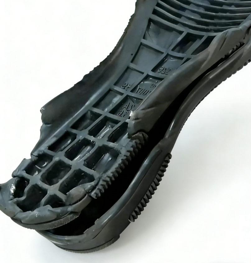
- Photos of the void after sectioning
Send these with the subject line “PU void diagnosis” to info@chinahaifeng.com or WhatsApp: 86 13566296633. You will get a process-level read, not a brochure answer.
Frequently Asked Questions
What is the difference between a void and a pinhole?
A pinhole is a small gas cavity that opens to the part surface. A void is internal and may or may not open to the surface. The formation mechanism can be similar; the difference is whether the gas had a path out.
What is the most common cause of voids in cast polyurethane?
Moisture in polyol or prepolymer is usually the first cause to rule out. After that, trapped air from mixing or mold fill and short shots are the most common mechanical causes.
Can too much mixing cause voids?
Yes. Mixing must create enough shear for homogeneity without folding air into the stream. A high mix-head speed that draws air into an unsealed or poorly flooded chamber can create bubbles that become internal voids.
How does shot weight relate to voids?
An undersized shot can leave the mold underfilled or slow the fill front so much that gel begins before gas escapes. Shot weight must include part volume, runner and overflow losses, and actual mixed-material density.
Can vacuum degassing always fix voids?
No. Vacuum degassing helps with dissolved gas and moisture, but it cannot fully compensate for a blocked vent, a wrong fill pattern, a metering-ratio excursion, or a short shot. Location and shape must guide the fix.
References
[1] G. Oertel, ed., Polyurethane Handbook, 2nd ed. Munich, Germany: Hanser Publishers, 1994.
[2] M. Szycher, Szycher’s Handbook of Polyurethanes, 2nd ed. Boca Raton, FL, USA: CRC Press, 2012.
[3] D. Randall and S. Lee, eds., The Polyurethanes Book. New York, NY, USA: Wiley, 2002.
[4] J. H. Saunders and K. C. Frisch, Polyurethanes: Chemistry and Technology, Part II. New York, NY, USA: Interscience, 1964.
[5] ASTM D792-20, Standard Test Methods for Density and Specific Gravity (Relative Density) of Plastics by Displacement, ASTM International, West Conshohocken, PA, USA, 2020.
[6] ISO 845, Cellular Plastics and Rubbers — Determination of Apparent Density, International Organization for Standardization, Geneva, Switzerland, 2006.
If you’re interested, check out these related articles:
How To Calculate Shot Weight In Polyurethane
How Polyurethane Rollers Are Made From Casting To Cure
Causes Of Shrinkage In Polyurethane Foam How To Control It
The Role Of Rise Time In Polyurethane Foaming