[Haifeng Process Standards Quick Reference]
Mechanical assembly accuracy in Haifeng polyurethane equipment is the physical foundation of metering accuracy. For every 0.05 mm by which the coupling misalignment between a servo motor and a metering pump exceeds the limit, the radial load on a plunger or gear pump can increase by 3–5 times. This can directly raise metered-flow fluctuation to more than 1.5% and reduce product density uniformity.
Key process parameters at a glance:
| Parameter | Haifeng standard | Industry reference | Related equipment accuracy indicator |
| Servo motor–metering pump coupling alignment (radial) | ≤0.03 mm | ≤0.05 mm | Metering ratio accuracy ±0.3% |
| Coupling alignment (angular) | ≤0.02 mm/100 mm | ≤0.05 mm/100 mm | Servo positioning accuracy ±0.1 mm |
| Metering pump installation level | ≤0.05 mm/m (longitudinal) | ≤0.05 mm/m | Plunger/gear pump volumetric efficiency ≥95% |
| Parallelism of the two linear-guide axes | ≤0.02 mm/m | ≤0.05 mm/m | Pouring-path repeatability ±0.05 mm |
| Ball-screw axial movement | ≤0.005 mm | ≤0.01 mm | Positioning-accuracy CV ≤1.5% |
| Metering-pump mounting-seat flatness | ≤0.02 mm | ≤0.05 mm | Ensures coaxiality of pump and motor shafts |
| Surface roughness of bearing-fit journals | Ra ≤0.8 μm | Ra ≤1.6 μm | Bearing temperature rise ≤15°C |
| Gear backlash (metering drive gears) | 0.03–0.08 mm (module 1–3) | 0.05–0.12 mm | Transmission backlash ≤0.05° |
| Seal-groove bottom roughness | Ra ≤0.8 μm | Ra ≤1.6 μm | Seal life ≥100,000 material shots |
| Assembly ambient temperature | 20±2°C | 20±5°C | Stable measurement reference for precision-fit parts |
| Fastening torque accuracy | ±3% of set value | ±10% | Consistent joint stiffness |
1. Scope
1.1 Applicable operations
This SOP applies to the following mechanical assembly operations for Haifeng polyurethane equipment:
| Assembly item | Key accuracy requirement | Related equipment performance indicator |
| Servo motor–metering pump drive system | Coupling alignment ≤0.03 mm | Metering ratio accuracy ±0.3% |
| Linear-guide/pouring-platform motion system | Parallelism ≤0.02 mm/m | Path repeatability ±0.05 mm |
| Ball screw–lifting/traverse axis | Axial movement ≤0.005 mm | Positioning-accuracy CV ≤1.5% |
| Metering-pump mounting base | Flatness ≤0.02 mm | Coaxiality of pump and motor shafts |
| Mixing head–valve body assembly | Clearance ≤0.02 mm | Reversing switching time ≤0.3 s |
| Material tank–pipeline sealing system | Seal-groove roughness Ra ≤0.8 μm | No leakage at 0.02 MPa in airtightness test |
| Frame–base installation | Level ≤0.05 mm/m | Servo mounting-datum offset ≤0.5 mm |
2. Pre-Job Preparation and Accuracy-Datum Verification
2.1 Review of technical documents
| No. | Document to check | Accuracy requirement | Acceptance criterion |
| 1 | Mechanical assembly drawing | Fit and geometrical tolerances are specified | Complies with GB/T 1800 and GB/T 1184 |
| 2 | Assembly process card | Key dimensions and assembly sequence are specified | Inspection points and tolerances included for key operations |
| 3 | Coupling-alignment record | Fields provided for radial/angular deviation | Complete and traceable record |
| 4 | Servo-motor parameter sheet | Matches the motor nameplate | Encoder resolution and rated torque are consistent |
| 5 | Bearing-clearance configuration sheet | Clearance class specified (C2/C3/C4) | Matches operating temperature |
2.2 Environmental conditions for precision assembly
Precision mechanical assembly must be performed in a controlled environment. Assembly stations for core transmission mechanisms must be clean and dust-free. Maintain an ambient temperature of 20±2°C and relative humidity of 40%–65%. Temperature fluctuations can thermally deform precision-fit parts and shift their measurement datum. Within 20±2°C, steel parts expand by approximately 0.024 mm per meter per °C; therefore, measure and record precision-fit dimensions under these temperature conditions.
2.3 Accuracy verification of tools and measuring instruments
| Tool/instrument | Accuracy requirement | Calibration interval |
| Electronic torque wrench | ±3% of set value | Every 3 months |
| Dial indicator/test indicator | 0.001 mm resolution | Every 6 months |
| Feeler gauge | 0.02 mm resolution | Every 6 months |
| Level | 0.02 mm/m resolution | Every 6 months |
| Coordinate measuring machine (CMM) | Spatial accuracy 1.7 μm | Every 12 months |
| Surface-roughness tester | Ra resolution 0.01 μm | Every 12 months |
3. Structured Mechanical Assembly Workflow
3.1 Establish assembly datums and clean parts
3.1.1 Locate assembly datums
Use the housing datum face and locating-pin holes as common assembly datums for core transmission mechanisms. Follow the datum-coincidence principle throughout assembly to reduce accumulated errors. Locating fixtures must provide high-precision stops. During clamping, ensure parts are fully seated without overhang, skew, or uneven loading. Recheck datum-location points periodically to maintain consistency and stability in long-term batch assembly.
3.1.2 Clean and inspect parts
Before assembly, ultrasonically clean precision parts with anhydrous ethanol or aviation kerosene; use a dedicated cleaning solution for hydraulic components. Dry parts with warm air to prevent residual moisture. Check critical dimensions with a micrometer and sample-check mating-surface roughness with a roughness tester. Bearing-fit journals must achieve Ra ≤0.8 μm, and bearing-seat bores must achieve Ra ≤1.6 μm. Recheck the actual interference of press-fit parts; the interference between a bearing inner ring and shaft must be ≥0.005 mm.
3.2 Assemble the servo motor–metering pump drive system (critical accuracy operation)
3.2.1 Mounting-base accuracy
The metering-pump mounting base must have flatness ≤0.02 mm, and parallelism between the pump and motor mounting faces must be ≤0.03 mm/100 mm. After installing the base, use a CMM or laser geometric measurement system to verify the spatial position accuracy of the mounting faces.
3.2.2 Install the metering pump
Install the pump on a rigid base 300–500 mm above floor level and level it. For multi-pump installations, use the coupling between adjacent pumps as the alignment datum. Permissible pump-body level deviation: longitudinal ≤0.05 mm/m; transverse ≤0.10 mm/m.
| Inspection item | Haifeng standard | Inspection tool |
| Longitudinal pump-body level | ≤0.05 mm/m | Precision level |
| Transverse pump-body level | ≤0.10 mm/m | Precision level |
| Perpendicularity of pump shaft to mounting face | ≤0.02 mm/100 mm | Dial indicator and master mandrel |
| Mounting-bolt torque | By size (M8: 25 N·m±1 / M10: 50 N·m±2) | Torque wrench |
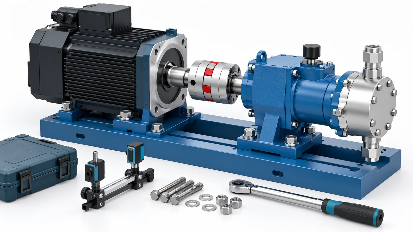
3.2.3 Coupling alignment (Haifeng critical accuracy operation)
Coupling-alignment accuracy directly determines the operating stability and metering accuracy of the pump. Keep coaxiality error between the metering-pump body and drive motor within 0.1 mm to prevent eccentric operation from causing gear wear and abnormal noise. Haifeng applies tighter limits: radial deviation ≤0.03 mm and angular deviation ≤0.02 mm/100 mm.
3.3 Assemble linear guides and ball screws
3.3.1 Install linear guides
Align the guide-rail datum face with the mounting datums on the worktable and base before fastening. Thoroughly clean mounting surfaces and remove burrs, scratches, and dirt.
Tighten the rail fasteners progressively from both ends toward the center. This helps maintain the best achievable running parallelism between the rail and its reference rail.
3.3.2 Install ball screws
The ball screw is a core transmission component for positioning accuracy. Ideally, there is no forward/reverse backlash between the screw and nut, and the support bearing maintains approximately 0.02 mm of interference preload to ensure stable, accurate transmission.
For long-travel ball screws, use a fixed-fixed mounting arrangement to reduce axial movement and increase axial rigidity. After installation, use a dial indicator to measure radial runout and axial movement at the screw end.
3.3.3 Connect the ball screw to the servo motor
Ensure coaxiality between the screw and motor shafts; measure and adjust it with a high-accuracy dial indicator. For direct-drive configurations, apply the coupling-alignment limits in Section 3.2.3 (radial ≤0.03 mm; angular ≤0.02 mm/100 mm).
3.4 Assemble gears and bearings
3.4.1 Assemble gears
Bring transmission gears into position smoothly. Never hammer or force-press them, which can damage tooth flanks and mating surfaces. After assembling a gear pair, rotate it manually or through the interlocked drive for inspection. It must run smoothly, without binding, abnormal noise, or abnormal radial movement.
| Module (mm) | Haifeng backlash standard (mm) | Industry reference (mm) |
| 1 | 0.03–0.05 | 0.03–0.08 |
| 2 | 0.05–0.08 | 0.06–0.12 |
| 3 | 0.06–0.10 | 0.08–0.15 |
Keep every meshing clearance within the process-design requirements; parts with out-of-tolerance clearance must not proceed to final-machine assembly. Apply the specified lubricant, in the specified quantity, evenly to the working tooth surfaces.
3.4.2 Assemble bearings
Control bearing clearance strictly. The tolerances of shafts and bearing housings used with precision bearings must be at least as accurate as the corresponding bearing bore and outside-diameter accuracy grades. Axial clearance is generally 0.05–0.15 mm (for C3 clearance). Temperature has a significant effect: for steel bearings, every 10°C increase in the inner-to-outer-ring temperature difference reduces clearance by approximately 0.01 mm. Select the correct clearance class for operating conditions.
| Inspection item | Haifeng standard | Inspection tool |
| Axial clearance | 0.05–0.15 mm (C3 class) | Dial indicator and dedicated fixture |
| Radial clearance | Corresponding class per GB/T 4604 | Feeler gauge or dedicated gauge |
| Fit between bearing outer ring and housing bore | H7 (transition fit) | Inside micrometer |
| Fit between bearing inner ring and shaft | k6 or m6 | Outside micrometer |
3.5 Assemble the sealing system
3.5.1 Seal-groove accuracy
Seal-groove machining accuracy directly determines sealing reliability. The back of a seal-installation groove must be vented to atmosphere. The peak-to-valley roughness (Rt) of sealing surfaces must not exceed 6.3 μm; the bottom of a counterbore is approximately 20–30 μm. For grooves that contact corrosive media such as MDI, Haifeng tightens the requirement to Ra ≤0.8 μm.
3.5.2 Install seals
Before installing a seal, check that the groove dimensions and accuracy meet the seal geometry requirements. The guide-strip groove must fit the guide strip closely, with no looseness. When installing polyurethane (TPU) seals, use a dedicated tool or protective sleeve to prevent damage to the sealing lip.
3.6 Integrate the complete machine
3.6.1 Install the frame and base
Frame level must be ≤0.05 mm/m. Tighten foundation bolts in stages and in a diagonal sequence with a torque wrench to avoid frame distortion from one-sided clamping. After frame assembly, use a laser tracker or CMM to measure the spatial position of the servo metering-pump mounting base and confirm datum-face offset ≤0.5 mm.
3.6.2 Match and integrate assemblies
When connecting subassemblies, align interfaces accurately and route pipelines without pulling, crushing, or bending damage. During housing closure and end-cover mating, apply force evenly and tighten in stages to avoid housing distortion or seal failure from one-sided clamping.
3.6.3 Run-in verification after assembly
After completing mechanical assembly of the full machine, perform an unloaded run-in test. Run the transmission at low speed (≤300 r/min) for at least 30 minutes. Monitor bearing temperature rise (≤15°C), RMS vibration velocity (≤2.8 mm/s, ISO 10816-3), and unloaded noise (≤75 dB(A)).
4. Key Parameters for Mechanical Assembly Accuracy
| No. | Accuracy category | Parameter | Haifeng standard | Inspection tool | Inspection frequency |
| 1 | Datum installation | Frame level | ≤0.05 mm/m | Precision level | 100% inspection |
| 2 | Datum installation | Metering-pump mounting-seat flatness | ≤0.02 mm | CMM/laser flatness gauge | 100% inspection |
| 3 | Drive system | Longitudinal metering-pump level | ≤0.05 mm/m | Precision level | 100% inspection |
| 4 | Linear motion | Parallelism of the two guide axes | ≤0.02 mm/m | Laser interferometer/dial indicator | 100% inspection |
| 5 | Linear motion | Ball-screw axial movement | ≤0.005 mm | Dial indicator | 100% inspection |
| 6 | Linear motion | Parallelism of screw and guide rail | ≤0.02 mm/1000 mm | Laser interferometer | 100% inspection |
| 7 | Gear transmission | Meshing backlash (module 1–3) | 0.03–0.10 mm | Feeler gauge/lead-wire method | 100% inspection |
| 8 | Bearing fit | Axial clearance (C3 class) | 0.05–0.15 mm | Dial indicator and fixture | 100% inspection |
| 9 | Bearing fit | Journal surface roughness | Ra ≤0.8 μm | Roughness tester | Sampling inspection |
| 10 | Sealing system | Seal-groove bottom roughness | Ra ≤0.8 μm | Roughness tester | Sampling inspection |
| 11 | Sealing system | Pipeline airtightness test | 0.02 MPa/30 min, no leakage | Pressure gauge and leak-detection fluid | 100% inspection |
| 12 | Environmental control | Assembly ambient temperature | 20±2°C | Temperature/humidity logger | Continuous monitoring |
| 13 | Fastening control | Torque deviation for critical bolts | ±3% of set value | Electronic torque wrench | 100% inspection and recording |
5. Common Problems and Process Pitfalls
5.1 Coupling misalignment reduces metering accuracy
Symptom: During operation, ratio accuracy gradually drifts from ±0.3% to above ±0.5%, and the metering pump develops abnormal vibration or noise.
Root cause: Coupling misalignment between the servo motor and metering pump exceeds the allowable range. Poor alignment causes bearing wear, seal failure, higher energy consumption, and potentially equipment damage. In a plunger pump, misalignment makes the applied drive force non-parallel to the pump-body axis and can deform the structure, reducing transmission accuracy.
Corrective actions:
1. Use a laser alignment tool for precision alignment: radial deviation ≤0.03 mm and angular deviation ≤0.02 mm/100 mm.
2. Recheck alignment after tightening the foundation bolts.
3. After alignment, rotate the shaft manually by two full turns and confirm there is no binding.
4. Recheck alignment every 500 operating hours or whenever abnormal vibration occurs.
5.2 Linear-guide parallelism error shifts the pouring path
Symptom: Pouring-path repeatability deteriorates from ±0.05 mm to more than ±0.1 mm, causing overflow at product edges or uneven filling.
Root cause: Linear-guide installation parallelism exceeds 0.02 mm/m. In a dual-axis guide system, insufficient parallelism creates a turning moment on the sliders as they move, diverting the worktable from its programmed path. Poor flatness of the guide mounting surface or an incorrect tightening sequence is a common cause.
Corrective actions:
1. Before installing the guides, confirm mounting-surface flatness ≤0.01 mm/500 mm.
2. Tighten strictly from both ends toward the center.
3. Measure parallelism between the two axes with a laser interferometer and confirm it is ≤0.02 mm/m.
4. Keep the height difference between the reference and driven guide rails ≤0.01 mm.
5.3 Ball-screw axial movement causes positioning variation
Symptom: A lifting or traverse axis drifts during repeated positioning, with a CV above 1.5%.
Root cause: Insufficient preload on the ball-screw support bearings or a loose locknut causes excessive axial movement. The amount of axial movement depends largely on the accuracy of the preload spacer. If axial clearance remains, the screw develops lost motion during reversal, directly causing positioning error.
Corrective actions:
1. Maintain 0.02 mm interference preload on the support bearings.
2. Measure axial movement at the screw end with a dial indicator; it must be ≤0.005 mm.
3. Secure the locknut with a dedicated anti-loosening measure, such as a lock washer or thread-locking compound.
4. Recheck axial clearance regularly and adjust promptly if it trends out of tolerance.
5.4 Incorrect bearing-clearance selection causes abnormal temperature rise
Symptom: Bearing operating temperature exceeds ambient by more than 25°C, or early fatigue flaking appears.
Root cause: The bearing clearance class does not match the operating temperature. Every 10°C increase in the inner-to-outer-ring temperature difference reduces clearance by approximately 0.01 mm. If a standard-clearance bearing is used in a high-temperature application, thermal expansion can eliminate clearance and place the bearing under interference, sharply increasing temperature.
Corrective actions:
1. Select the correct clearance class for the operating temperature (use C3 or C4 for high-temperature conditions).
2. Before assembly, use a pneumatic gauge to measure shaft/bore tolerances; the accuracy must reach IT6–IT7.
3. Measure actual clearance after assembly and confirm it is 0.05–0.15 mm.
4. Monitor bearing temperature rise during run-in. Stop and inspect if it exceeds 15°C.
5.5 Seal damage during installation causes early leakage
Symptom: MDI leakage appears at a pipeline joint or mixing head after several weeks of operation.
Root cause: The sealing lip is scratched by a groove edge or sharp thread during installation. Although polyurethane seals have excellent wear resistance, they are sensitive to shear damage during installation, especially thin-lip designs used in high-pressure sealing locations.
Corrective actions:
1. Before installation, check that groove edges are smoothly chamfered; finish them with a fine oilstone if necessary.
2. Use a dedicated installation tool or thin-wall protective sleeve to guide the seal over threaded sections.
3. Apply lubricant compatible with the process medium to the sealing lip before installation.
4. Perform an airtightness test immediately after assembly. If leakage is found, disassemble and inspect the seal.
5.6 Uncontrolled ambient temperature affects precision fits
Symptom: Precision assemblies from the same batch show inconsistent readings on a temperature measuring instrument, and some fit clearances fall outside tolerance.
Root cause: The assembly workshop does not meet the required temperature/humidity conditions, or the metrology room is not temperature-stabilized, causing dimensional measurement errors. Steel expands by approximately 0.024 mm per meter per °C between 20°C and 30°C. For a precision fit with only 0.005 mm interference, a 2°C temperature deviation can change the fit condition.
Corrective actions:
1. Equip precision-assembly stations with temperature/humidity loggers and monitor and record conditions continuously.
2. Measure precision-fit parts at 20±2°C.
3. Allow parts brought in from outside to acclimate in the assembly room for at least two hours.
4. Before assembling an interference fit, record part temperatures and actual interference.