
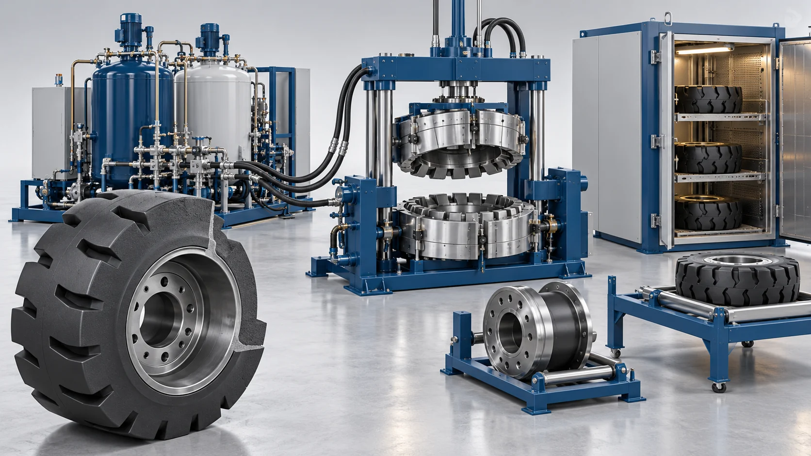
Construction Equipment Solid PU Wheel Molding Solution
Configure molded PU wheels for the specified worksite equipment using part drawings, material-processing data, hub preparation and a defined casting and curing sequence.
Worksite Construction Equipment PU Wheel Manufacturing Configuration
Configure molded PU wheels for the specified worksite equipment using part drawings, material-processing data, hub preparation and a defined casting and curing sequence.
Wheel Assembly Requirements
Define geometry, hub fit, load, speed, terrain and chemical exposure for the actual component. Equipment selection is based on these inputs.
Process and Equipment Scope
Identify metering, mixing, tooling, handling and post-treatment in the agreed equipment schedule. Listed case or brief values describe their own configurations.
Define the supplied equipment, installation, commissioning, operator training and service responsibilities in the project agreement.
Worksite PU Wheel Casting Workflow
Coordinate the wheel assembly and material requirements through the selected production sequence.
Prepare the Hub and Mold
Select cleaning, primer, preheating and mold preparation for the hub, formulation and wheel geometry.
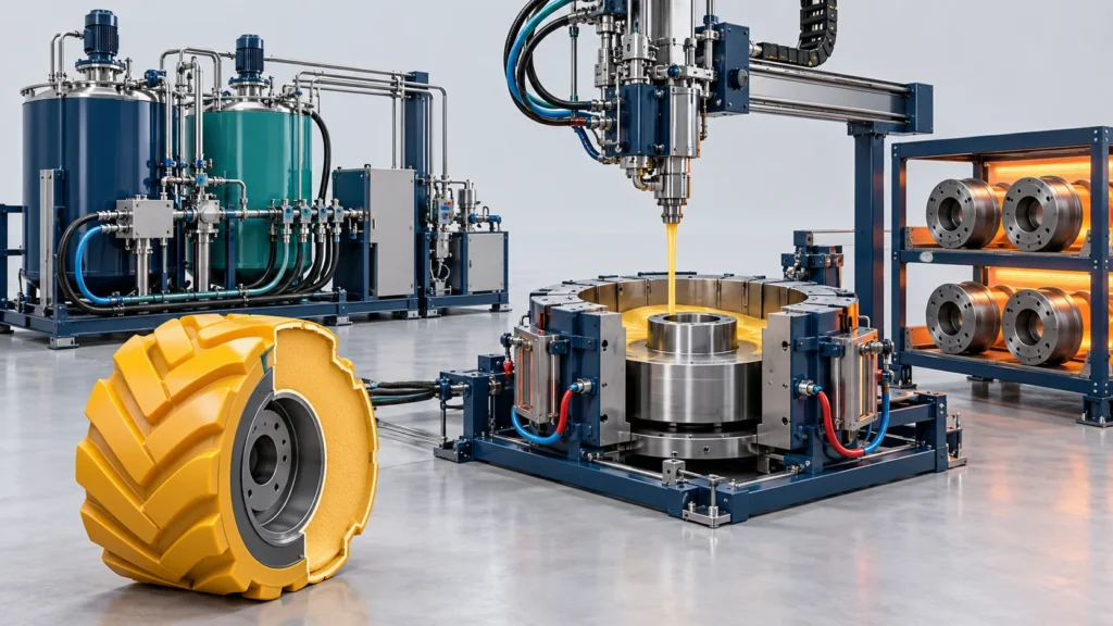
Meter, Mix and Fill
Choose compatible metering and mixing, set the shot from the wheel cavity and validate the filling sequence.
Cure in the Selected Tooling
Coordinate the mold arrangement and thermal conditions with the formulation and required demolding readiness.
Configuration References and Selection Conditions
Equipment ranges are supplied-brief references. Wheel load, wear and environmental performance require component-specific evaluation.
| Item | Reference / Selection Input | Conditions |
|---|---|---|
| Application | Specified worksite transport and construction wheels | Define the actual wheel and operating duty. |
| Material | Selected cast PU formulation; brief hardness reference Shore A 80–92 | Final material processing and properties follow the selected formulation. |
| Density reference | Formulation-specific | Any numerical range is from the supplied configuration brief, subject to formulation trials. |
| Diameter reference | 12–33 inches | Brief configuration range; tooling and hub geometry are selected separately. |
| Metering output reference | 25–70 kg/min | Brief equipment reference, not finished wheels per hour. |
| Submitted time reference | 6–9 min | Original timing endpoints require confirmation. Record entry-to-demold cycle separately from output interval. |
| Load, wear and chemical resistance | Specified for the actual wheel assembly | No universal load rating, comparative wear-life multiplier or chemical-resistance outcome is asserted. |
Production Planning Considerations
Match process functions to the specified wheel and factory requirements.
Hub and Tooling Interfaces
Coordinate part drawings, hub preparation, molds and demolding.
Material Processing
Select metering, mixing and thermal settings for the formulation.
Production Organization
Plan station count, mold cavities, working hours and downstream stages.
Component Evaluation
Define the load, wear, bonding and exposure tests relevant to the actual wheel.
Related Project Case
Explore related project references. Each project has its own configuration, reference values and evidence conditions.
Frequently Asked Questions
Process selection, tooling, commissioning and line integration.
Does this page establish a wheel load or wear-life rating?
Can one equipment configuration cover every wheel size?
How is production output calculated?
What information is needed for process selection?
Discuss Your Tire and Wheel Production Project
Send wheel and hub drawings, material data, operating duty, shot size, mold cavities, daily working hours, target output and factory layout to define the configuration.


