
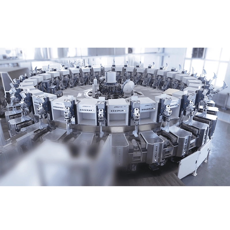
Triple-Density Injection Machine | Footwear
Assess triple density direct injection equipment with 24 or 30 stations. Review sole layers, material circuits, automation scope and trial requirements.
Product, Application and Configuration
Assess triple density direct injection equipment with 24 or 30 stations. Review sole layers, material circuits, automation scope and trial requirements.
Product Overview
A triple density direct injection machine is intended for footwear soles with different densities in defined layers or zones. It has 24 or 30 station configurations, PLC control and servo motor drive. Define each layer before selecting the processing units. Density count, color count and raw-material circuit count are separate requirements; material compatibility depends on the actual configuration and molding trials.
Applications
- Footwear projects with three density zones or layers.
- Multilayer soles requiring a defined molding sequence.
- Multi-density product development involving material and interlayer bonding trials.
For a simple single-material sole, compare the required functions with a simpler configuration. Additional density capability is useful only when it matches the intended product structure.
Configuration and Selection
Create a layer-by-layer specification that records material, density, thickness, weight and color. Review the required plasticizing or metering units, material circuits and mold movements for that structure. Define the order of molding stages and the time assigned to each stage.
Validate one footwear design and material combination before expanding the product range. Interlayer bonding and appearance should be checked on molded samples before using the proposed cycle time as a production basis.
Define the automation scope for feeding, upper preparation, pouring, removal and inspection before selecting stations or robotic equipment.
Discuss Your Project
Send a sole section drawing with the material, target density, thickness, weight and color of each layer. Add the size range, output target and preferred automation scope so the processing units, mold sequence, station configuration and trial plan can be reviewed together.
Technical Specifications
The material list does not establish that one standard configuration processes all four materials.
| Technical Parameter | |
|---|---|
| Density capability | Triple density and multi-density, subject to the selected process configuration |
| Station options | 24 or 30 |
| Control and drive | PLC control; servo motor drive |
| Operating mode | Automatic operation; individual tasks and operator involvement require definition |
| Material routes for technical review | PU, TPU, PVC and TPR; compatibility must be confirmed separately for each configuration |
| Numerical operating limits | Flow rate, clamping force, mold frame dimensions, power and cycle time require confirmation |
Key Features
Review these functions against the selected material, tooling and operating scope.
Defined density structures
Triple-density and multi-density configurations for defined sole structures.
Rotary station options
A choice of 24 or 30 stations.
PLC and servo drive
PLC control and servo motor drive.
Optional robotic pouring
Optional robotic pouring; confirm the robot and dispensing scope.
Defined automation scope
Automatic operating concept with remaining manual tasks to be defined.


