
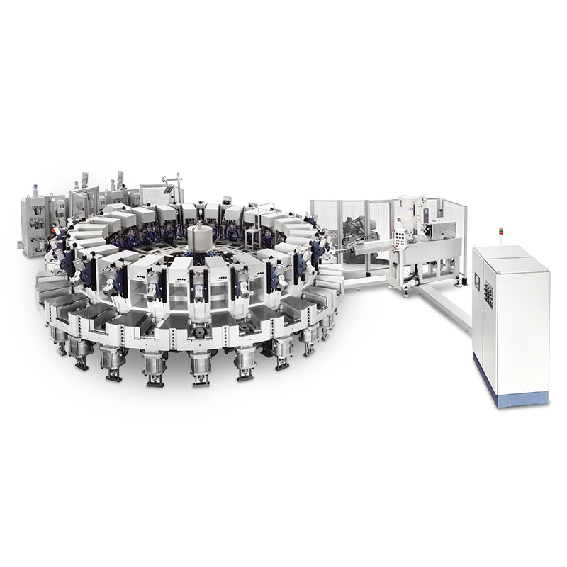
PU/TPU Direct Injection Machine | Composite Soles
Review the JG116/PU-TPU direct injection machine for composite soles, with 24 or 30 stations, separate PU and TPU processing data, and selection guidance.
Product, Application and Configuration
Review the JG116/PU-TPU direct injection machine for composite soles, with 24 or 30 stations, separate PU and TPU processing data, and selection guidance.
Product Overview
The JG116/PU-TPU is a TPU PU direct injection machine for footwear soles combining thermoplastic polyurethane (TPU) and polyurethane (PU). Separate PU feeding and TPU plasticizing units need to match the weight and processing requirements of each material layer. The machine has 24 or 30 station options, with mold frame dimensions listed below. Selection starts with the sole structure and material grades, followed by the molding sequence, tooling and cycle schedule. Suitability for a specific footwear design requires process confirmation and sample trials.
Applications
The machine is intended for TPU and PU composite sole projects. Define the role of each layer through the product design, including thickness, color, cushioning and abrasion requirements. Material properties and finished footwear tests determine the resulting performance.
For safety footwear projects, assess the intended sole construction and applicable product testing separately from equipment selection.
Configuration and Selection
Start with a sole layer drawing showing material grades, layer weights and thicknesses. Then define the molding sequence, bonding method, mold movements and upper positioning. Check each processing unit against its own required shot size and processing time.
Match station count to the complete cycle schedule. Review TPU processing, PU dispensing, molding dwell, indexing and manual operations separately. The layout should identify operating space and access around the equipment.
For existing molds, compare frame dimensions, gates, opening and closing movements, layer structure and upper positioning. Matching the outside dimensions alone does not establish compatibility.
Discuss Your Project
Share the sole layer drawing, material grades, weight of each layer, upper material and target shift output. Include existing mold drawings and available installation space to request a configuration review and sample trial plan.
Technical Specifications
PU feed rate is a mass rate; TPU plasticizing capacity is a volumetric rate. These figures describe different processing units and cannot be combined into one machine output figure.Clamping force and screw or component dimensions require technical confirmation. Overall dimensions, installed power and measured energy consumption are not specified here.
| Technical Parameter | JG116/PU-TPU |
|---|---|
| Stations | 24 or 30 |
| Mold frame dimensions | 200 × 400 mm or 200 × 430 mm |
| PU feed rate | 20–60 g/s |
| TPU plasticizing capacity | 50 cm³/s |
Key Features
Review these functions against the selected material, tooling and operating scope.
Separate material units
Separate PU feed rate and TPU plasticizing capacity figures for checking each processing unit against its layer requirements.
Rotary station options
A choice of 24 or 30 stations for matching the molding sequence and operating layout.
Process controls
Temperature control, hydraulics and movement measurement for managing the molding process.
Mold frame options
Two listed mold frame sizes for initial tooling compatibility review.


