Plant buyers often treat pouring head and mixing head as alternate names for the same part. They occupy different positions in the material path and fail in different ways. The mistake usually appears at specification time: the quote covers the right pump set but the wrong head configuration, and only later shows up as density bands, trapped air, or uneven cavity fill.
Where the Two Terms Actually Separate
In a low-pressure polyurethane machine, the metering pumps deliver the A-side and B-side into a motor-driven pin mixer. That pin mixer is the mixing head. It is where the components meet, begin to react, and form the first uniform blend. After the mixer, the liquid enters the pouring head, which shapes and deposits the mixed material into the mold. The pouring head is a distribution device more than a mixing device.
In high-pressure reaction injection molding systems, the mixing head is more visible in the literature. Two pressurized streams impinge in a small chamber at pressures typically in the 10–20 MPa window, and a cleaning piston evacuates the chamber at the end of each shot [3]. The mixed material may then pass through a runner or manifold to a nozzle or pouring head. Again, mixing and pouring are separate functions even when they share one housing.
Practically, the distinction means two inspection questions. If the issue is incomplete reaction, ratio striping, or wet look, you inspect the mixing head. If the issue is fill pattern, knit lines, or density bands that follow the pour path, you inspect the pouring head.
The Engineering Difference
| Variable | Mixing head | Pouring head |
|---|---|---|
| Primary role | Bring A and B together with enough energy for uniformity | Lay mixed material into the mold with a controlled flow path |
| Feed condition | Separate reactive streams | Already mixed liquid |
| Key design input | Chamber volume, pin count or impingement pressure, recirculation | Nozzle or slot geometry, stroke pattern, pour angle |
| Typical failure | Ratio striping, residual reactivity, chamber contamination | Splashing, uneven laydown, air entrainment, flow marks |
| Cleaning logic | Solvent/air purge or impingement piston clean | Air purge, solvent flush, or manual wipe depending on design |
The choice is rarely mixing head versus pouring head. A production line needs both. The real decision is which function constrains the design first, because that changes the machine architecture and the quoted components.
Variables That Decide the Head Configuration
The first input is material. High-viscosity, filled, or highly reactive systems behave differently from unfilled low-viscosity systems. Mechanical low-pressure mixing heads tolerate abrasive fillers and wide mixing ratios more easily, while impingement mixing heads need tight recirculation and sealing to keep pressure stable [1]. If the formulation includes short fibers or paste pigments, the head must be designed for wear and short clean cycles.
Shot size and cycle time come next. A small shot with a fast cure requires a head that can be cleaned without losing more material than the part is worth. A large shot with a slow cure may allow a simpler low-pressure mixer but require a robust pouring head to spread material without trapping air.
The numerical A:B ratio is only as reliable as the isocyanate content determination behind it [5]. If the raw-material certificate does not match the actual supply, even a well-designed mixing head cannot correct the chemical imbalance.
Mold geometry is the third input. A single open cavity is forgiving; a six-cavity sole mold or a wide slab mold can produce fill variation even when mixing quality is excellent. In these cases, the pouring head path, dwell time, and nozzle geometry often matter more than extra mixer energy.
Before changing hardware, confirm that the shot volume itself is correct. A well-mixed stream deposited by a well-designed pouring head will still short-fill or overfill if the shot programming is wrong.
If the component ratio looks correct but cavity fill is inconsistent, the problem is often shot-size calculation rather than the head design. How To Calculate Shot Weight In Polyurethane covers how to verify shot volume before chasing hardware changes.
If the head is already being changed, send Haifeng the part drawing, shot weight, mixing ratio, and cycle time before the purchase order is finalized. A head sized without those inputs is a recurring maintenance cost. Contact Info@chinahaifeng.com or WhatsApp: +86 13566296633 with the data, and the head configuration will be specified against the metering pump set and mold flow path rather than as a standalone item.
Applications: When the Pouring Head Carries the Decision
For multi-cavity footwear molding, a walking pour head or multi-nozzle setup distributes material so that all cavities start reacting on nearly the same schedule. The mixing head must produce a uniform blend, but the fill difference between cavities is driven by pour path and dwell.
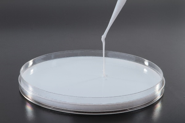
For slabstock and insulation panel lines, the pouring head frequently becomes a wide-slot or trough distributor. Material leaving a well-mixed stream still has to be spread into a large mold or moving facing sheet without leaving banded density. As foam expands, the initial liquid distribution follows the pour pattern, so a trough that is not level or a slot that is too narrow can create visible density structure later.
For open-mold elastomer casting, the pouring head often determines whether air is trapped at the surface. Low, steady pour rates and the right nozzle angle allow the liquid front to advance instead of folding over itself. The mixing head matters, but the visible defect is a pouring-head defect.
If cream and rise timing are on target but density distribution varies, examine the pour pattern before changing mixer speed. The reaction profile interacts with the physical distribution of the liquid, not just the quality of the mix.
If cream time and gel time are correct but density varies across the part, the pour path usually has more influence than mixer RPM. The Role Of Rise Time In Polyurethane Foaming covers how reaction timing interacts with liquid laydown.
When the Mixing Head Carries the Decision
High-output closed-mold lines lean toward self-cleaning impingement mixing heads because the piston clean cycle supports short repeats without a lengthy solvent purge [3]. The mixing chamber is small, pressure is high, and mixing energy comes from impingement rather than a motor-driven pin. This works well for clean formulations, tight cycles, and automated lines.

Low-pressure mechanical mixing heads still dominate process windows that need wide ratio flexibility, abrasive fillers, or frequent formulation changes. The mixer must be purged and cleaned more often, but the head is often easier to service and cheaper to replace. In one Haifeng automotive buffer line, the same pump set produced acceptable parts with a small-volume pin mixer, but even cavity fill across a multi-cavity mold depended on a matching distribution pouring shoe rather than extra mixer speed. That is the practical distinction: the mixer made the material uniform; the pouring head made the mold uniform.
Polyurethane chemistry also sets a boundary. Once the polyol and isocyanate meet, viscosity rises and gel begins. A mixing head that leaves poor residence-time distribution can produce hard and soft domains in the same part [2]. That is why chamber volume should stay as small as practical relative to shot volume, especially for fast systems where the mixed stream is close to gel by the time it reaches the mold [1][4].
Head-Related Defects and Where to Look
| Defect | First place to inspect |
|---|---|
| Ratio striping or streaky color | Mixing head chamber, recirculation valve, pump synchronization |
| Wet or soft spots in cured part | Mixing quality, component temperature, mixer speed |
| Density bands following pour path | Pouring head slot, trough level, pour speed |
| Air entrapment or surface pinholes | Pour angle, nozzle distance, mold venting |
| Cavity-to-cavity fill variation | Pour path, nozzle timing, shot programming |
A common mistake is replacing the mixing head when a pouring head issue is the actual cause. If foam collapses or shrinks unevenly after demold, the defect is rarely a single component change. The reaction, the pour pattern, and the mold temperature act together.
When voids or sinks appear after demold, a poorly matched pouring head flow path can seed the density gradients that shrinkage later makes visible. Causes Of Shrinkage In Polyurethane Foam How To Control It covers the process adjustments that reduce those gradients.
Decision Framework: Spec the Part, Then the Head
Start with the part and shot, not with the head catalog. The same machine can support multiple head styles, but the useful choice narrows quickly once mold layout, shot weight, and formulation are fixed.
| Condition | Lean toward |
|---|---|
| Short cycle, closed mold, clean formulation, high output | Self-cleaning impingement mixing head with fixed or robotic pouring nozzle |
| Filled or abrasive formulation with wide ratio range | Low-pressure metering plus motor-driven pin mixing head |
| Wide slab or panel requiring even laydown | Mixing head plus wide-slot or trough pouring head |
| Multi-cavity mold with fill variation | Metering pumps matched to multi-port or walking pouring head |
| Frequent color change or small batch | Head with active recirculation and short clean cycle |
The pouring head and mixing head are not competitors in the same category. They are adjacent parts of one delivery chain. When a line produces uneven parts, the diagnosis must separate mixing failure from distribution failure before a single component is exchanged.
For a head recommendation matched to your existing pumps, send Haifeng the part drawing, shot weight, mixing ratio, and cycle time at Info@chinahaifeng.com or WhatsApp: +86 13566296633.
FAQ
Is a pouring head the same as a mixing nozzle?
No. A pouring head can include a nozzle, but its function is downstream distribution. A mixing head receives separate A and B streams and must make them chemically uniform before the liquid reaches the mold.
Can I use a high-pressure mixing head on a low-pressure machine?
Usually not. High-pressure impingement mixing relies on pressures and flow paths that a low-pressure metering set cannot deliver, and low-pressure mechanical mixing requires different cleaning and recirculation logic. Changing one component without the supporting hydraulic and control design creates new failure modes.
Where should I clean first when density bands appear?
Check the pouring head slot, trough level, and pour speed first. Density bands that follow the liquid flow path usually point to distribution, not incomplete mixing. If bands appear as streaky color inside the part rather than along the pour path, inspect the mixing head and recirculation system.
Does a larger mixing chamber improve mixing?
Not necessarily. A larger chamber can increase residence time, but it also increases the volume that must be purged or cleaned and can broaden residence-time distribution. Chamber volume should be large enough for the target flow and stream energy, not used as a substitute for correct metering and mixer speed.
References
[1] G. Oertel, Ed., Polyurethane Handbook: Chemistry, Raw Materials, Processing, Application, Properties, 2nd ed. Munich: Hanser Publishers, 1994.
[2] P. Król, “Synthesis methods, chemical structures and phase structures of linear polyurethanes. Properties and applications of linear polyurethanes in polyurethane elastomers, copolymers and ionomers,” Progress in Materials Science, vol. 52, no. 6, pp. 915–1015, 2007.
[3] C. W. Macosko, RIM: Fundamentals of Reaction Injection Molding. Munich: Hanser Publishers, 1989.
[4] S.-T. Lee and D. P. Scholz, Eds., Polymeric Foams: Technology and Developments in Regulation, Process, and Products. Boca Raton: CRC Press, 2009.
[5] ISO 14896:2009, Plastics — Polyurethane raw materials — Determination of isocyanate content, International Organization for Standardization, Geneva, 2009.
If you’re interested, check out these related articles:
How To Calculate Shot Weight In Polyurethane
SRIM Explained Structural Reaction Injection Molding Basics