
Haifeng PU foaming convention: A = polyol blend; B = isocyanate. Other suppliers may use different letters; verify actual tank labels and material documentation. CPU prepolymer and curative streams are identified by material name.
A polyol that meters cleanly at 35°C can starve the same gear pump at 18°C. Viscosity is rarely the headline specification on a polyurethane machine, but it determines whether the metering pump holds ratio, whether the mixing head generates enough energy to homogenize the stream, and whether the delivery path survives the first cold start of the shift. The useful question is not “what is the viscosity,” but “how wide is the viscosity window across the temperatures, fillers, and production speeds you actually run?”

Viscosity Is a Process Variable, Not a Material Constant
Viscosity is a fluid’s resistance to shear. In urethane raw-material work it is usually reported as dynamic viscosity in mPa·s, measured by a defined method at a stated temperature. A data sheet that reports a single Brookfield value at 25°C gives a starting point, but it does not describe the process window [3]. Rotational viscometry with a defined shear rate is standardized in ISO 3219 [1], and incoming polyol acceptance testing commonly follows ASTM D4878 [2].
Three facts matter more than the data-sheet number. First, filled polyol systems may be shear-thinning, so the apparent viscosity changes with pump speed and mixer speed. Second, viscosity is strongly temperature-dependent; a few degrees of sidewall cooling in a feed line can create a local high-viscosity slug that the pump sees as a pressure spike. Third, the B-side isocyanate and A-side polyol almost never move on the same viscosity-versus-temperature curve. When one side thins faster during warm-up, ratio control becomes a moving target.
That asymmetry is the real equipment problem. A machine may hold ±0.3% metering accuracy during a steady-state trial and then drift during production warm-up, filler change, or day-tank refill because the viscosity state changed before the control loop did.
How Viscosity Drives Metering and Pump Selection
Positive-displacement gear pumps do not make viscosity irrelevant. A low-viscosity fluid allows internal slip, which shows up as ratio creep. A high-viscosity filled A-side can starve the pump inlet, causing cavitation, erratic delivery, and accelerated gear wear. Both conditions look the same in a production log: ratio drift with no obvious mechanical fault.
The equipment selection sequence should therefore begin with the material window, not the pump catalog. For each component, the operator should define the viscosity range at minimum start-up temperature and at normal operating temperature. The pump must be selected for the highest viscosity the line will actually see, while the flow-meter and servo-control strategy must remain stable at the lowest viscosity and highest speed.
Mass-flow and volumetric metering diverge when density changes with temperature and fillers. Viscosity affects both methods indirectly: it changes fill speed, nozzle backpressure, and whether the meter sees a steady or pulsating stream. A gravity-corrected mass flow reference is often more useful than a nominal displacement reading when viscosity is variable.
Viscosity changes the meaning of a correct shot, because mass and volume metering drift apart when density and flow behavior shift together. How To Calculate Shot Weight In Polyurethane covers the calculation that should precede any metering calibration.
Temperature Control, Mixing Head, and Delivery Path: One Viscosity System
Temperature control is viscosity control. A raw-material preheating oven, heated day tank, and heated hose set are not accessories when the A-side contains high-viscosity polyols or fillers; they are part of the metering chain. At start-up, the cold mass in the feed line and mixing head behaves like a different material. The most common field failure seen is not pump selection, but cold spots: a poorly insulated hose run, a metal fitting outside the heated zone, or a day tank setpoint that works for the tank thermocouple but not for the material near the outlet.
Recirculation becomes more important as viscosity rises, because line pressure drop increases. A recirculation loop sized for a low-viscosity trial may lose enough pressure to alter nozzle flow when the production formulation is thicker. The question to ask is not “can the machine pump it,” but “can the machine recirculate it at the lowest operating temperature without exceeding the pressure or torque limits.”
Mixing-head selection follows the same viscosity curve. Low-pressure mechanical mixing is more tolerant of high viscosity and filled systems because the motor drives a physical mixer. High-pressure impingement mixing is faster and self-cleaning, but it depends on two high-velocity streams colliding well enough to mix by kinetic energy. If one stream is much more viscous than the other, the impingement field collapses into a dominant stream and mixing quality falls long before the pressure gauge alarms.
Temperature corrections change viscosity and foaming response at the same time. The Role Of Rise Time In Polyurethane Foaming covers how a warmer or cooler material stream changes the rise profile.
Mixing Head Selection: Low-Pressure vs. High-Pressure
The operating choice between low-pressure and high-pressure heads should not be made on output rate alone. Low-pressure heads can push highly filled, abrasive, or viscous systems through a broader viscosity range, but they normally require solvent flushing and generate more cleaning downtime. High-pressure heads offer self-cleaning, rapid cycle times, and compact mixing chambers, but their useful viscosity window is narrower and more sensitive to A/B viscosity mismatch.
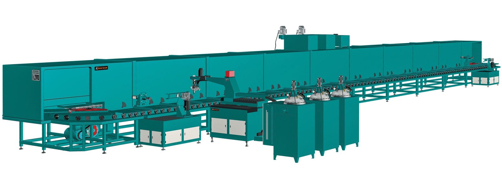
In practice, a high-pressure machine is less forgiving when the A-side thickens. The nozzle pressures may be set for a 20–45°C conditioned material. If the material arrives colder, its viscosity rises, the pressure ratio shifts, and the mix quality can degrade even though the metering pumps still display the same throughput. Precision pouring nozzles are part of the answer; small nozzle-geometry changes affect the pressure-velocity profile and how viscosity is converted into mixing energy. In one rail-pad installation, a purpose-designed precision pouring nozzle helped the line hold stable pouring from a compact rotary-disc configuration [4].
When fiber loading enters the formulation, viscosity management moves from simple temperature adjustment to the core mixing strategy. RRIM Vs RIM Which Process Suits Your Structural Part covers the trade-off between reinforced and unfilled processing routes.

A Practical Viscosity-Driven Equipment Checklist
Before selecting or troubleshooting a machine, resolve these seven points in order:
- Measure viscosity at three temperatures: minimum start-up, normal operation, and upper conditioning limit. Note the method, spindle, and shear rate.
- Confirm whether the material is Newtonian or shear-thinning. If the fillers settle or the reading changes with speed, specify the shear rate for future comparisons.
- Decide whether the line will meter by mass or volume, and check whether density correction is needed for the expected temperature range.
- Size suction lines, pump clearances, and recirculation loops for the highest viscosity, not the trial formulation.
- Compare B-side and A-side viscosity curves at start-up and operating temperature. Flag any ratio where one side changes much faster than the other.
- Choose the mixing head by viscosity window and cleaning tolerance together, not by output rate alone.
- Specify a cold-start procedure: preheat time, recirculation warm-up, and when the first shot may be released.

A fifteen-minute viscosity review
If a machine is already installed and ratio drift appears only during start-up or after filler changes, do not begin by changing the pump. Pull the raw-material TDS, mark the viscosity at the actual operating temperature, and note any filler or moisture changes. If the answer is not obvious from those data, email both component TDS sheets and a viscosity-versus-temperature curve to Info@chinahaifeng.com. A useful review starts with the material window, not with a replacement quote.
Working Out Your Viscosity Window
If you are specifying new polyurethane equipment or correcting an unstable existing line, the fastest path is to define the viscosity window before locking machine size. Send the following to Info@chinahaifeng.com or reach out on WhatsApp at +86 13566296633:
- Both component TDS sheets, including viscosity method and temperature.
- Filler type, loading, and any known shear-thinning behavior.
- Required output in kg/min or shot weight per cycle.
- Lowest material temperature the line will see at start-up.
- Current metering accuracy or known ratio drift data.
A practical evaluation should close with a metering, mixing, and delivery recommendation tied to those values, not to a generic output figure.
Frequently Asked Questions
Does higher viscosity always require a low-pressure mixing head?
Not always. Low-pressure mechanical heads generally tolerate a wider high-viscosity range, but high-pressure heads can process viscous systems when the material is conditioned consistently, the nozzle geometry is correct, and the A/B viscosity mismatch is controlled. The choice depends on the full viscosity curve and cleaning requirements, not viscosity alone.
What viscosity method should I trust on a raw-material TDS?
Use the supplier-reported dynamic viscosity in mPa·s as a starting point, but ask for the method, temperature, spindle, and shear rate. A single Brookfield value cannot distinguish Newtonian from shear-thinning behavior, so a shear sweep is more useful when fillers or pigments are present [3].
How much does temperature affect viscosity during production?
The exact shift depends on the formulation, but the effect is usually large enough that a cold feed line or unheated hose becomes the root cause of pressure spikes and ratio drift. Because the B-side and A-side rarely shift at the same rate, temperature control should be treated as part of ratio control.
Why does recirculation matter more at high viscosity?
Higher viscosity increases pressure drop through the same hose diameter, so a loop that was stable in a low-viscosity trial may not recirculate the production formulation at the same flow rate. At the design stage, recirculation should be sized for the highest viscosity expected at the lowest operating temperature.
References
- ISO 3219:2013, Plastics — Polymers/resins in the liquid state or as emulsions or dispersions — Determination of viscosity using a rotational viscometer with defined shear rate.
- ASTM D4878-15, Standard Test Methods for Polyurethane Raw Materials: Determination of Viscosity of Polyols.
- DIN EN ISO 2555:2018, Plastics — Resins in the liquid state or as emulsions or dispersions — Determination of apparent viscosity using the Brookfield test method.
- Zhejiang Haifeng Automation Equipment Co., Ltd., “Precision pouring nozzle,” Chinese Patent ZL 201611168678.6.
If you’re interested, check out these related articles:
Measuring Polyurethane Foam Resilience A Practical Test Guide
Causes Of Shrinkage In Polyurethane Foam How To Control It
What Is Spray Polyurethane Foam Composition And Application
The Role Of Rise Time In Polyurethane Foaming