
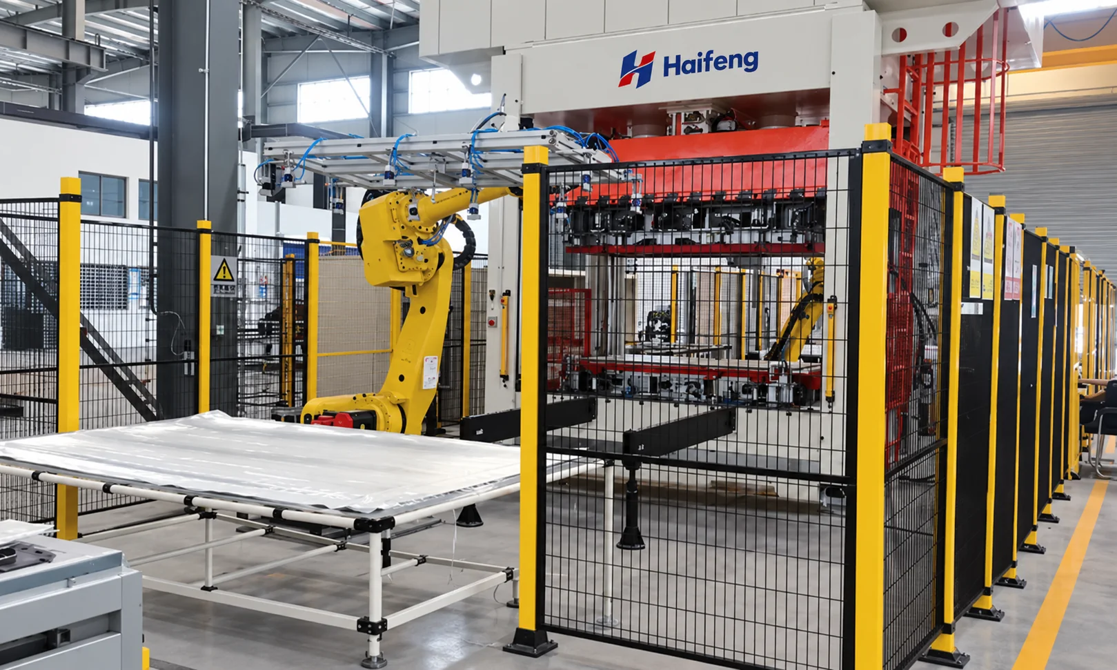
HP-RTM Automatic Preforming Solution
A turnkey automated preforming line for carbon- and glass-fiber woven fabrics, preparing continuous-fiber-reinforced parts for HP-RTM molding.
Prepare Fiber Reinforcement for HP-RTM Molding
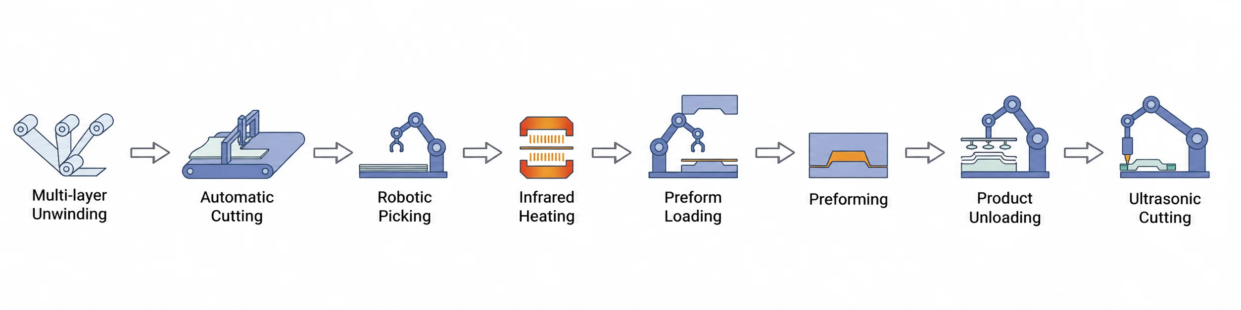
HP-RTM (high-pressure resin transfer molding) uses high pressure to mix and inject resin into a vacuum-sealed mold preloaded with fiber reinforcement. The resin flows through and impregnates the preform, cures, and is then demolded. This automated preforming line prepares carbon-fiber and glass-fiber woven fabrics through multi-layer unwinding, cutting, heating and preforming. It supports thermoset resin matrix and continuous-fiber-reinforced products before molding. The turnkey project can cover design, manufacturing, transport, unloading, installation, commissioning and training.
Reinforcement and preform first
Define the woven-fabric reinforcement, layup, preform geometry and acceptance requirements before selecting unwinding, cutting, heating and handling interfaces.
Balance upstream and downstream capacity
Measure the cycle from entry into the station through demolding. Output per cycle depends on the mold cavity arrangement, typically one part per cycle. Daily scheduling is one shift or a 10-hour working day. Balance upstream and downstream station capacities, and confirm annual working days, availability, yield and changeovers before committing to annual output.
The line integrates multi-layer unwinding, cutting, heating and preforming for thermoset resin matrix and continuous-fiber-reinforced products. Project scope can include design, manufacture, transport, unloading, installation, commissioning and training.
Woven-Fabric Preparation and Preforming Workflow
Prepare the woven-fabric reinforcement for downstream HP-RTM molding. This upstream sequence covers fabric handling, cutting, heating and preforming; resin metering, injection, cure and final-part demolding belong to the separately defined molding cell.
Multi-layer unwinding
Synchronize the supplied woven-fabric layers and feeding arrangement for the selected reinforcement.
Cutting and layer fixation
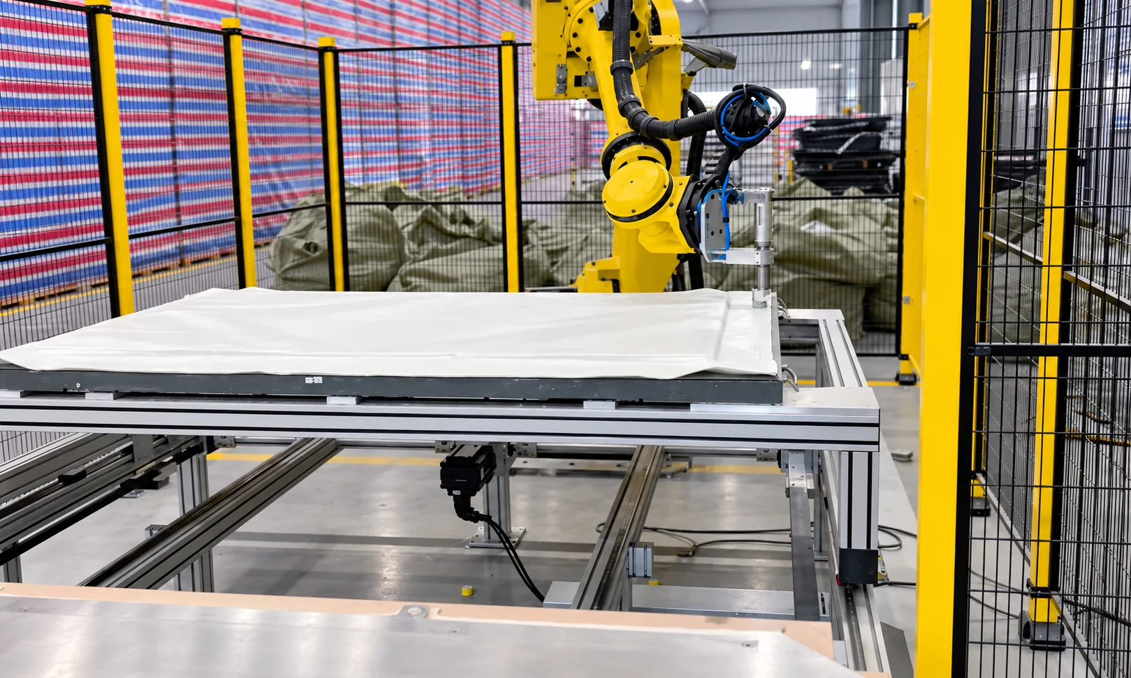
Cut and secure the stack using the configured cutting and ultrasonic spot-welding interfaces.
Transfer to heating
Coordinate robotic handling and the fabric transfer path with the heating station.
HP-RTM Preforming Line — Reference Parameters
Line configuration and reference values for preparing woven-fabric reinforcement before HP-RTM molding.
| Parameter | Reference specification |
|---|---|
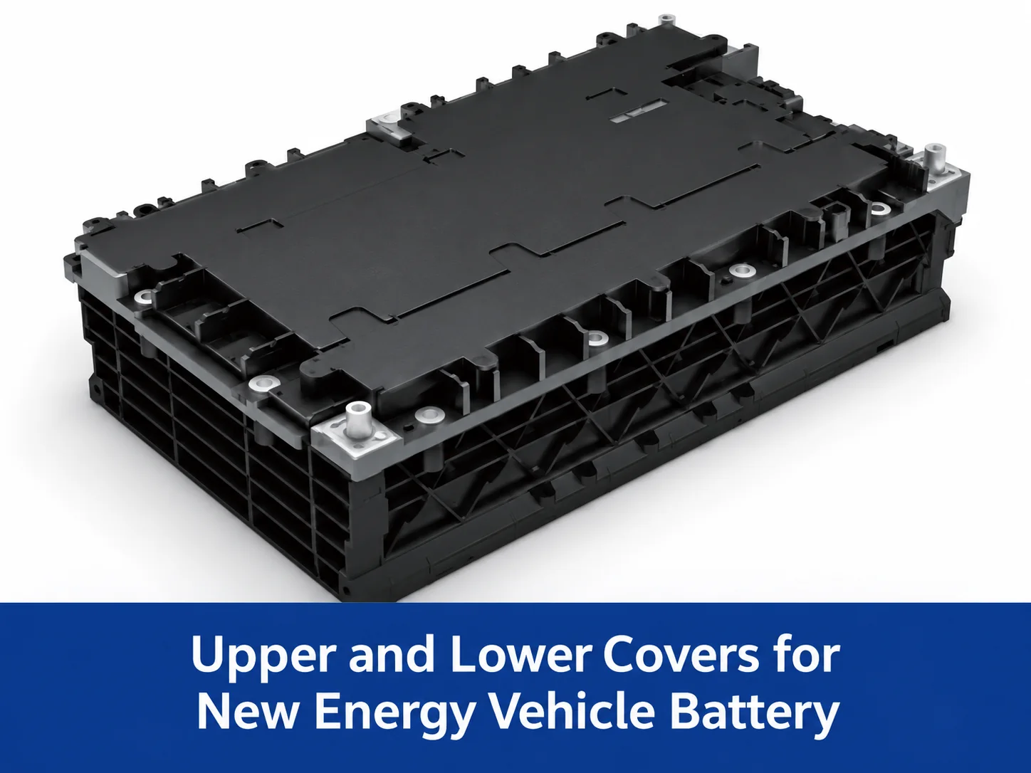
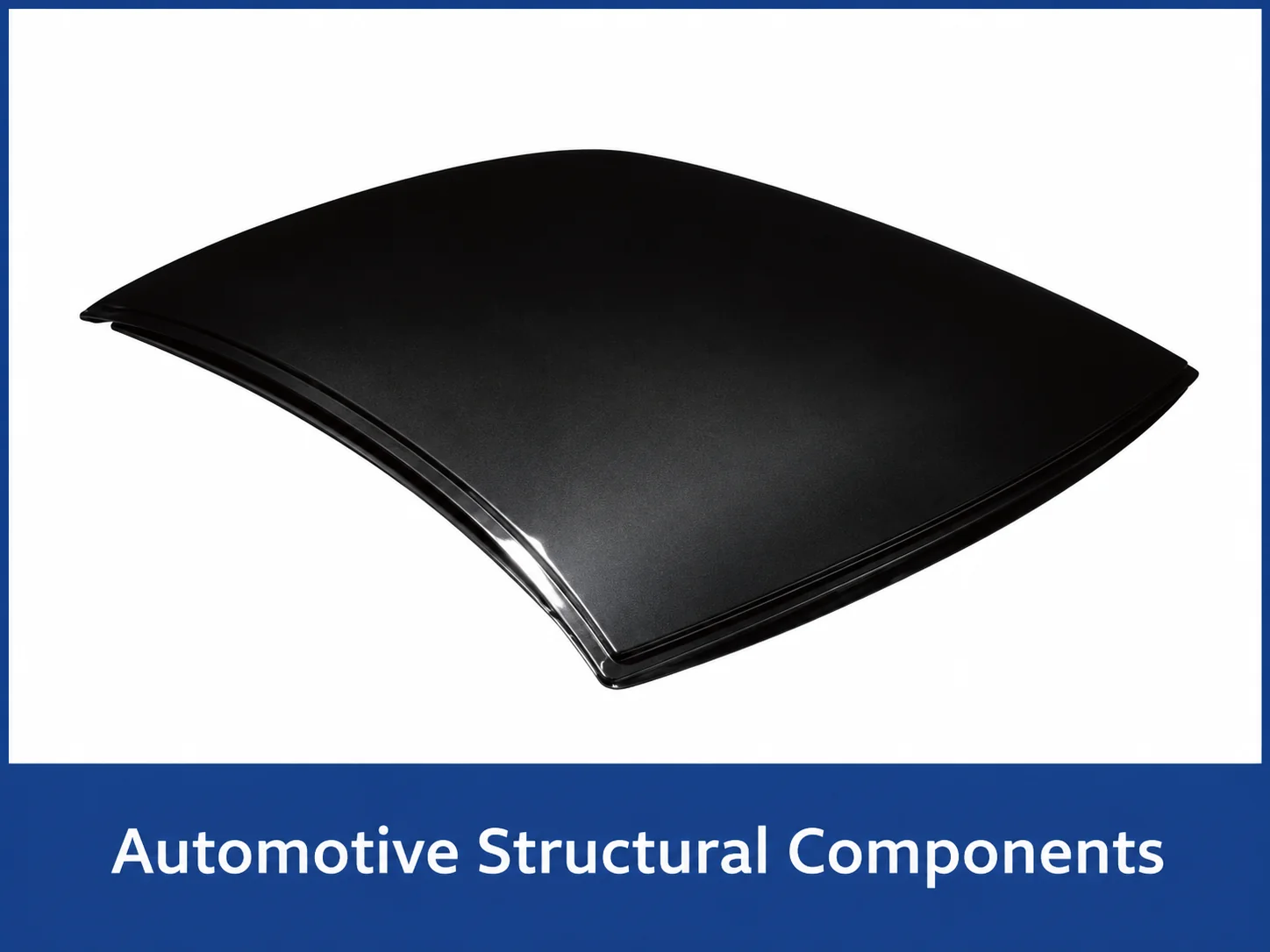
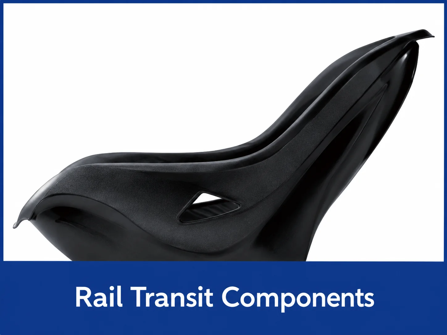
| Industry applications | New-energy vehicle battery covers and trays; automotive structural components; aerospace parts; rail-transit components |
| Preforming-line cycle and capacity reference | 2–4 minutes per cycle, measured from entry into the station to demolding. Output per cycle depends on the mold cavity arrangement; one part per cycle is typical. The stated daily schedule is one shift or a 10-hour working day. Approximately 100,000 preforms per year remains a supplied reference; annual working days, equipment availability, yield and production interruptions must be agreed before treating it as a production commitment. |
| Applicable reinforcement | Carbon-fiber and glass-fiber woven fabrics |
| Automation | 100% automated line |
| Multi-layer unwinding | Up to 6 woven-fabric layers can be automatically laid and synchronized at the same time |
| Ultrasonic welding | Ultrasonic spot welding secures the stacked layers |
| Infrared heating oven | Settable from ambient temperature to 450°C; accurate temperature control and high temperature uniformity |
| Control system and communication | SIEMENS / AB control brands; PROFINET / EtherNet/IP industrial Ethernet real-time communication |
| Flash-trimming dimensional accuracy | ±0.2 mm |
These reference specifications are supplied for this line. The project proposal defines the final process sequence and acceptance conditions.
HP-RTM Preforming Line — Concept Illustrations
Concept illustrations only; these are not photographs of delivered equipment or customer installations.
Coordinate the Equipment With the Process
Evaluate repeatability, handling and acceptance across the full workflow.
Reinforcement-specific preparation
Fabric layers, cutting, heating and preforming interfaces are selected for the reinforcement and preform design.
Defined downstream interfaces
Preform transfer and station capacities are coordinated with the separately specified HP-RTM molding cell.
Documented acceptance
The proposal defines cycle measurement boundaries, operating assumptions, inspection responsibilities and preform-specific acceptance.
Related Project Records and Industry References
Related cases describe application-specific HP-RTM molding workcells. Their finished-part cycle and performance do not establish the output of this upstream preforming line; review the separate station capacities and project conditions.
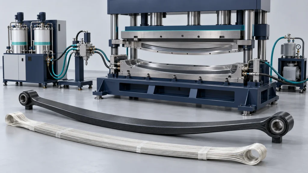
Heavy-Duty Composite Leaf Spring HP-RTM Line Project in China
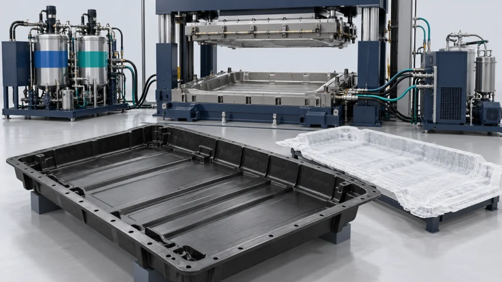
Automotive EV Battery Enclosure HP-RTM System Project in China
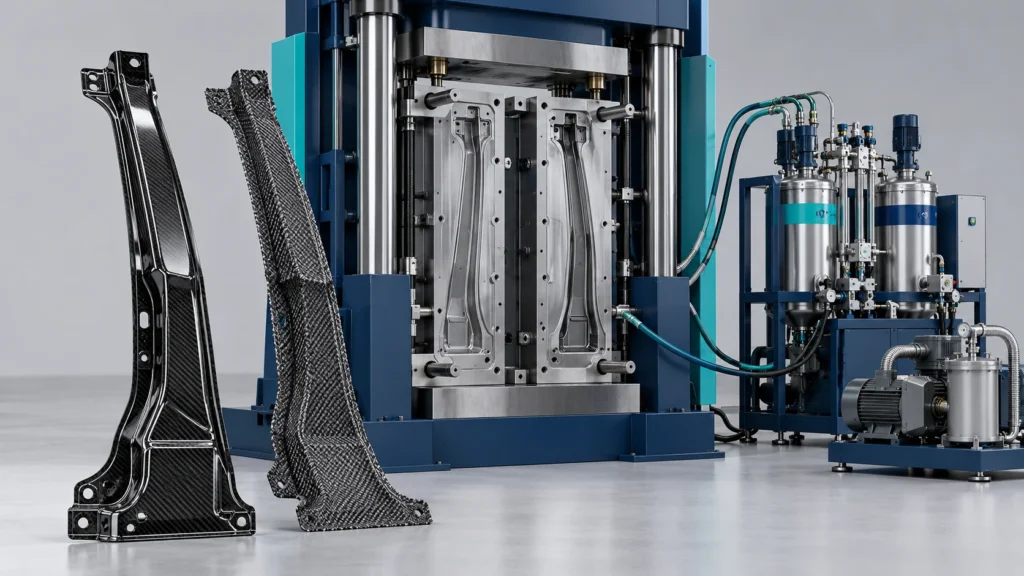
Automotive Carbon Fiber B-Pillar HP-RTM Line Project in China
Frequently Asked Questions
Clarify the production route before selecting a machine.
Does high-pressure mixing specify the cavity pressure?
What information is needed to size the production line?
What is included in the equipment package?
Are cycle time and finished-product performance fixed?
Submit Your Production Goals
Share the finished product, material, target capacity, automation requirements and factory conditions to discuss a project-specific line configuration.


