
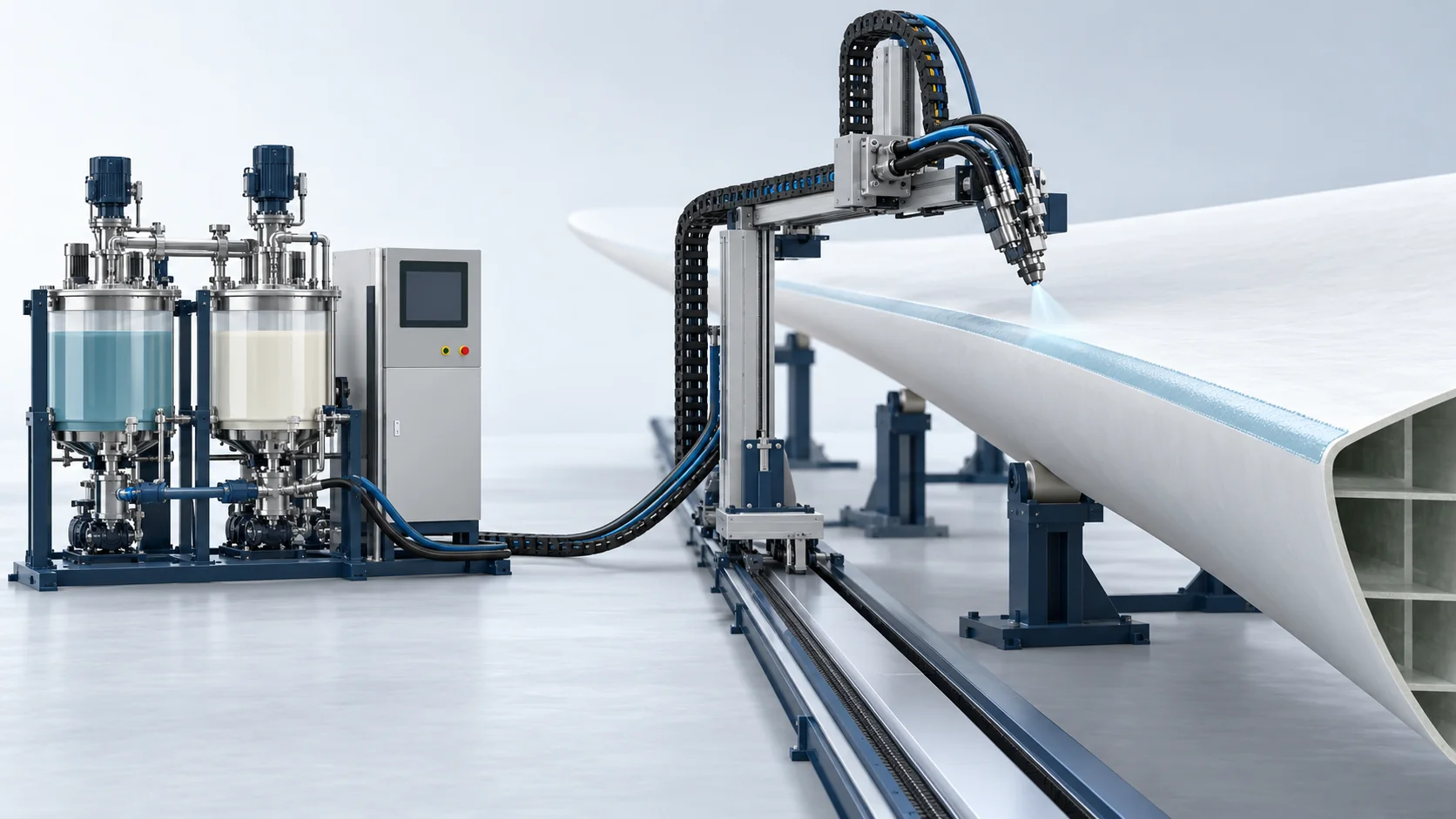
Servo Coating Spray Machine | Wind Blade Leading Edges
Servo-metered spraying for the polyaspartic resin/aliphatic-isocyanate leading-edge coating described in the supplied brief. Robotic tracking and film inspection are separately specified options.
Polyaspartic Coating Application Configuration
Servo-metered spraying for the polyaspartic resin/aliphatic-isocyanate leading-edge coating described in the supplied brief. Robotic tracking and film inspection are separately specified options.
Servo-metered spraying for the polyaspartic resin/aliphatic-isocyanate leading-edge coating described in the supplied brief. Robotic tracking and film inspection are separately specified options.
Confirm the actual coating TDS, component compatibility, metering ratio, atomizing arrangement and operating window for the selected material. Coating laboratory results are material/substrate references, not equipment performance or turbine-energy claims.
Material Flow and Working Principle
Prepare the Surface
Define surface preparation and the selected coating application path.
Servo Metering
Condition, meter and mix the selected coating components within the calibrated operating window.
Temperature Control
Set material temperature from the selected coating processing data.
Apply the Coating
Coordinate atomization and traverse with the coating and blade geometry.
Cure and Inspect
Follow the material-specific cure, then inspect film build and surface condition.
Model and Technical Parameters
Configuration references from the supplied HF-WND80-SRV brief. Pressure circuit designation, output, heating and hose capability require confirmation under the stated operating conditions. Coating properties and laboratory qualification belong to the selected material/substrate system and require original reports.
| Technical Parameter | HF-WND80-SRV |
|---|---|
| Components | 2 Components (A: Polyaspartic resin, B: Aliphatic isocyanate) |
| Output Range (g/s) | 0.5 to 4.5 kg/min (Continuous micro-adjustable) |
| Mixing Ratio Range | 100:40 to 100:100 (By weight) |
| Ratio Accuracy | ±0.2% (Servo closed-loop continuous mass tracking) |
| Power Supply | 380V, 3-Phase, 50Hz (Custom 440V/480V 60Hz optional) |
| Working Pressure | 10.0 to 14.0 MPa (Servo fluid delivery lines) |
| Tank Capacity (L) | Day tanks: 2 x 60 L (Stainless steel with N2 purge) |
| Weight | 850 kg (Base mobile proportioning skid) |
| Dimensions (L×W×H) | 1600 mm x 1100 mm x 1550 mm |
| Pressure Pulse Fluctuation | < ±0.1 MPa (At 12.0 MPa operating pressure); Servo direct-drive gear pumps |
| Coating Dry Film Thickness | 300 µm ± 20 µm (Single-pass controlled traverse); Laser confocal thickness gauge |
| Submitted Material Rain-Erosion Reference | 120 m/s, 15 h and no reported pitting in the supplied brief; specimen, coating, cure and original test report are pending. This is not an equipment rating or field-life claim. |
| Submitted Airfoil-Test Reference | <0.2% in the supplied brief; test geometry, definition and original records are pending. This is not a turbine-energy gain claim. |
Key Equipment Features
The package covers servo metering, temperature-conditioned passages, the specified atomizing head and controls. Gantry tracking and non-contact film measurement are optional. Polyaspartic coating is supplied by the selected material supplier; clean surface-preparation facilities and conditioned compressed air are customer interfaces. Coating qualification and aerodynamic results require component-specific records.
Servo Metering
The specified feed-control system manages the selected coating ratio and calibrated delivery window.
Film-Build Control
Traverse, atomization and inspection are configured against a dry-film target; wet-film settings are established separately.
Rain-Erosion Test Evidence
Laboratory erosion testing is specific to the coating, substrate, cure and test conditions and requires original reports.
Airfoil Evaluation Evidence
Surface profile and wind-tunnel results are component-specific; a spray configuration alone does not establish turbine energy yield.


