
Five-Component High-Pressure PU/PIR Foaming System | Sandwich Panels
Five-component PU/PIR metering for sandwich panels, with independent polyol, isocyanate, catalyst and blowing-agent circuits, flow monitoring and line integration.
5 components
Independent main-material and additive circuits
19–30 kg/min
Reference output; size to panel demand
6–20 MPa
Adjustable injection pressure
Material Preparation, Metering and Laydown
Five-component PU/PIR metering for sandwich panels, with independent polyol, isocyanate, catalyst and blowing-agent circuits, flow monitoring and line integration.
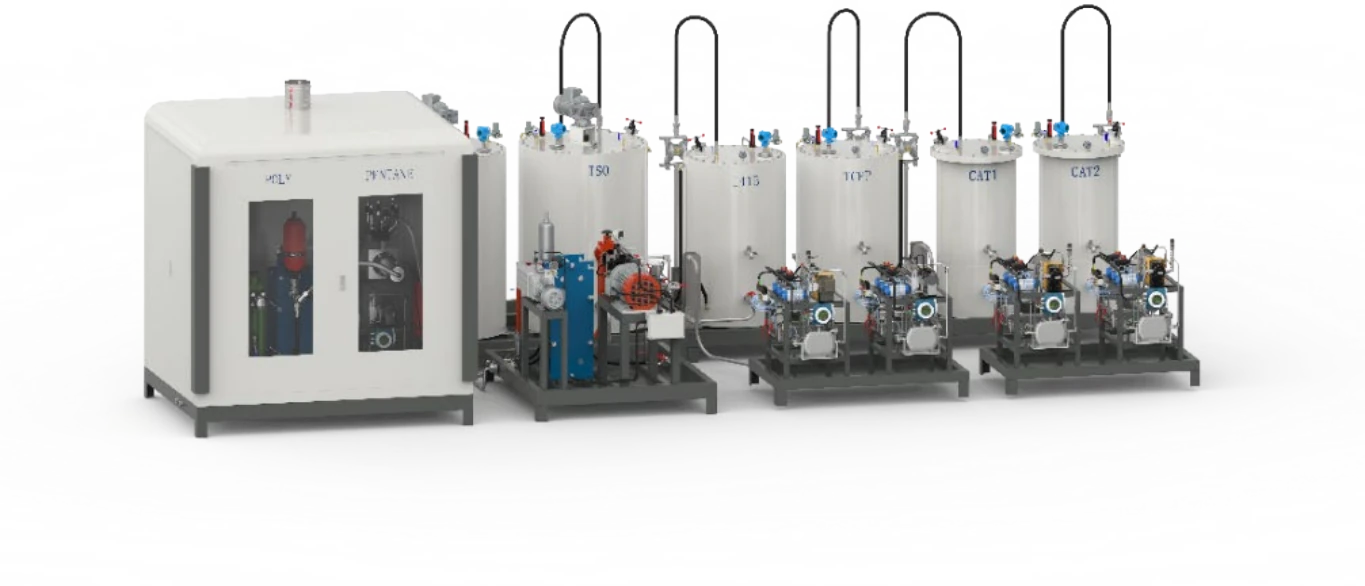
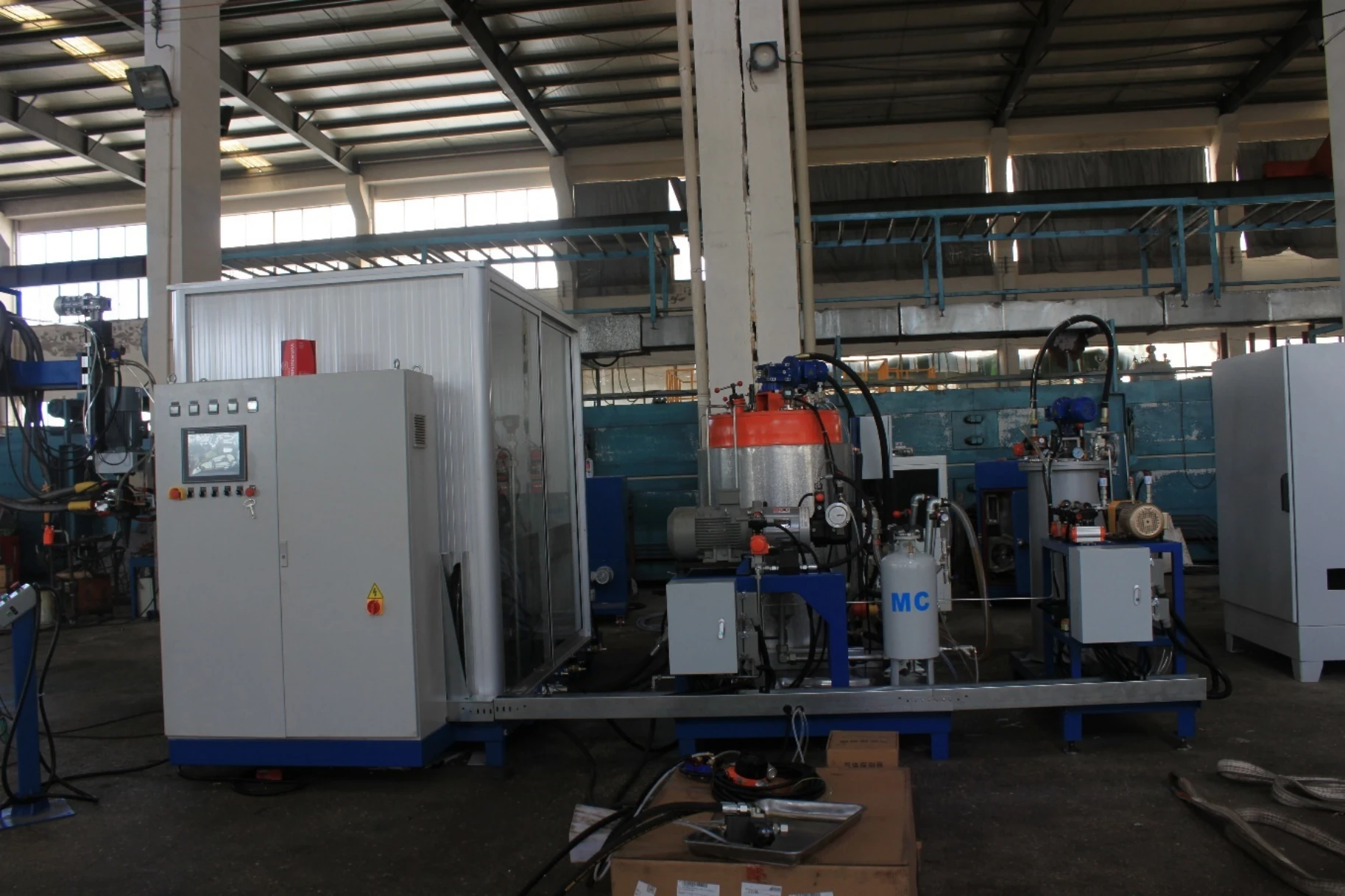
The HF-HPC-50-CS reference is a five-component high-pressure polyurethane metering and mixing system for metal-faced PU/PIR sandwich panel production. Separate circuits meter polyol, isocyanate, two catalysts and a pentane blowing-agent stream. Component flow feedback, material conditioning and circulation are coordinated with the selected formulation and production line.
The supplied reference specifies 19–30 kg/min injection output and an adjustable injection-pressure range of 6–20 MPa. The metering package can work with a stationary or traversing laydown head, while refill equipment and heating/cooling units maintain material supply. Output must be sized against panel width, thickness, foam density and line speed.
Pentane handling uses a separately specified enclosure, gas monitoring, ventilation and interlock scope. Material-tank volumes, mixing-head model and utility loads are finalized in the configuration schedule.
Explore the industrial sandwich panel production solution.
Material and Injection Workflow
Condition and refill
Prepare component materials, establish circulation and maintain tank temperature and refill levels.
Meter and verify
Calibrate independent component deliveries and select the recipe and injection settings.
Mix and distribute
Coordinate the high-pressure mixing head and stationary or traversing laydown with the panel line.
Reference Configuration
Configuration-specific data from the supplied technical brief. Component selection, tank schedule and flow calibration are agreed for the material formulation.
| Technical Parameter | HF-HPC-50-CS |
|---|---|
| Components | 5: polyol, isocyanate, catalyst 1, catalyst 2 and pentane blowing agent |
| Output Range (g/s) | 19–30 kg/min reference injection output; final selection depends on panel duty |
| Mixing Ratio Range | Stated adjustable range 5:1–1:1; component order and ratio basis confirmed with the formulation |
| Ratio Accuracy | Separate mix-ratio accuracy not specified; confirm by component-flow calibration |
| Power Supply | 380 V, 50 Hz, three-phase; approximately 40 kW reference package power |
| Working Pressure | 6–20 MPa adjustable injection pressure |
| Tank Capacity (L) | Independent component tanks; final volumes and vessel schedule confirmed for the ordered configuration |
| Weight | Approximately 3,000 kg, reference configuration |
| Dimensions (L×W×H) | Final equipment footprint and maintenance clearances from approved layout |
| Shot repeatability | Specified ≤±1%; test conditions agreed for the selected materials |
| Injection timer | 0.5–99.99 s; 0.01 s setting resolution |
| Operating mode | Continuous injection and manual injection program |
| Material temperature | 22°C reference conditioning point; ±2°C stated control deviation |
| Flow control | Component flow feedback to PLC with independent pump-delivery adjustment |
| Hydraulic unit | 15 L/min; 5.5 kW motor in the reference configuration |
| Compressed air | Dry, oil-free; 0.45 MPa and 600 NL/min reference demand |
| Blowing-agent dosing | Dedicated pentane metering circuit; pump, enclosure and monitoring selected for the project |
| Head and laydown system | High-pressure mixing head; stationary or traversing installation selected for line width and speed |
| Refill systems | Polyol refill and pneumatic diaphragm feed circuits coordinated by level signals |
| Temperature-control package | Tank conditioning and air-cooled chiller; final heating duty and chiller rating confirmed in the utility schedule |
Metering and Integration Functions
Five Independent Component Circuits
Polyol, isocyanate, two catalysts and blowing agent have individually specified metering and feed paths.
Component Flow Feedback
Flow signals coordinate pump delivery with the selected recipe, while component tests provide calibration references.
Material Conditioning and Refill
Tank conditioning, level indication and refill equipment support continuous component availability.
Circulation and Head Coordination
High/low-pressure circulation switching and mixing-head operation follow the PLC injection sequence.
Line Laydown Interface
Stationary and traversing head arrangements are sized for the facing-sheet width, shot requirement and production speed.
Blowing-Agent Monitoring Interfaces
Pentane metering, enclosure ventilation, gas monitoring and stop/interlock actions are specified together in the project scope.


