When foam density drifts while the control panel still shows a stable ratio, the usual suspect is not the formulation. It is the component in the metering chain that turns the setpoint into actual volume: the pump. On many polyurethane foaming machines, that component is a gear pump.
In a two-component system, the isocyanate and polyol streams must be delivered in a repeatable ratio through changing viscosity, temperature, and mixing-head backpressure. An external gear pump is a positive-displacement machine: each revolution traps and transfers a defined geometric volume, so at constant speed it supplies near-constant flow only as long as internal leakage remains small [1]. That characteristic makes the gear pump a useful metering and feed element, but only when slip is understood and controlled.
The gear pump is not just a flow source. It influences the pressure seen at the mixing head, determines shot-to-shot consistency, and wears in ways that quietly change the effective ratio. Selection and maintenance therefore matter as much as the catalog displacement curve.
Where Gear Pumps Sit in the Metering Chain
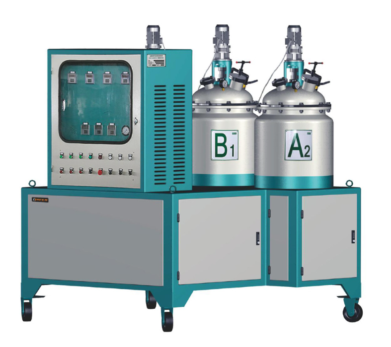
Gear pump placement depends on machine pressure class. In many low-pressure and medium-pressure foaming machines, gear pumps are the direct metering elements for the A and B streams. In high-pressure machines, they are more commonly feed or recirculation pumps that supply servo-controlled metering cylinders or axial-piston metering pumps. This distinction is important because a gear pump that works well as a boost pump may not be the best final metering device when very short shots and extremely tight ratio tolerance are required.
Within the metering loop, the gear pump sits after the material day tank and conditioning system and before the mixing head or dosing chamber. Its job is to push a stable volume against whatever backpressure the head, hose, nozzle, and material viscosity create. Because output is based on trapped volume rather than centrifugal force, the gear pump is less sensitive to downstream pressure than a centrifugal pump would be [1]. That is why it appears so often in polyurethane machinery.
Ratio Control Under Foaming Backpressure
The control panel may hold pump speed constant, but the actual flow can still move. Internal clearance leakage, commonly called slip, increases as discharge pressure rises and as fluid viscosity falls. When the mixing head begins to restrict, when a filter loads, or when material temperature drifts upward, the same pump speed can deliver less usable volume.
This creates a difficult failure pattern: the machine may report stable pump speed while shot weight and density change gradually. A well-designed metering system addresses this with pressure feedback, servo speed correction, or calibrated slip compensation. Even so, wear can change the slip curve over time. That is why ratio verification should be based on actual shot weight and flow rate, not only on a stable speed signal.
A stable pressure reading on the machine display can mask changing flow behavior as the formulation reacts and viscosity shifts. <The Role Of Rise Time In Polyurethane Foaming> covers viscosity and reaction timing signals that help separate pump drift from process drift.
Selecting Gear Pumps for A-Side and B-Side
The two material streams create different pump requirements. Polyol blends may be filled, higher-viscosity, and abrasive, while isocyanates are moisture-sensitive and often lower-viscosity [2]. The same pump model may not be ideal on both sides without careful material review.
| Selection factor | Polyol / B-side | Isocyanate / A-side |
|---|---|---|
| Typical viscosity trend | Higher; may be filled or pigmented | Lower; usually more temperature-sensitive |
| Clearance strategy | Wider internal clearances if fillers are present | Tighter clearances reduce slip on low-viscosity fluid |
| Wetted materials | Hardened steel or wear-resistant construction | Moisture-compatible treated steel, stainless, or plated surfaces |
| Seal and shaft area | Mechanical seal rated for the polyol temperature band | Shaft seal and reservoir design must exclude atmospheric moisture |
| Relief protection | Required to protect the pump when head or line blocks | Required, with relief routed to a safe return |
Selection that looks reasonable on a datasheet can still be wrong if the viscosity curve crosses the pump clearance assumptions. If you are switching from an unfilled to a filled polyol or changing A-side temperature control, send the formulation TDS and current pump displacement to Info@chinahaifeng.com or WhatsApp:+86 13566296633 before committing to a machine specification.
Common Failure Modes and What They Do to Shot Weight
Gear pump wear rarely announces itself. Tooth-tip erosion, end-plate scoring, and bearing play all enlarge the clearances that control internal leakage. A shaft seal leak on the A-side may admit moisture and gradually change material reactivity; on the B-side, air ingress can create density variation and poor cell structure.
Cavitation is another gear pump failure mode. It occurs when suction pressure falls too low, often because of a blocked filter, overly long suction line, high material viscosity, or operating speed beyond the pump’s inlet capability. The resulting flow instability shows up as short shot weight, noisy operation, and pressure spikes at the mix head.
When metering slip changes, the first visible result is often a shift in part weight or foam density before the machine alarm triggers. <Causes Of Shrinkage In Polyurethane Foam How To Control It> covers process-side conditions that interact with metering stability and mold fill.
Sizing Checks That Prevent Oversized or Starved Pumps
Gear pump sizing begins with the relationship between displacement per revolution, operating speed, and required shot flow. For a given output, the pump should run within its recommended speed band and leave margin above minimum flow and below maximum speed. Performance curves should be used instead of nominal displacement alone, because slip is not a fixed percentage across speed and pressure [1], [3].
An oversized pump run at very low speed can produce poor low-flow repeatability, longer material recirculation, and unnecessary heating. An undersized pump run near maximum speed is more likely to cavitate, overheat, and wear quickly. Matching the pump to the shoot weight and cycle time prevents both failure patterns.
Shot weight is the translation point between pump displacement and usable foam output. <How To Calculate Shot Weight In Polyurethane> covers the calculation logic, including mold fill, flash allowance, and cycle timing.

Get a Metering Check Against Your Actual Process
At Haifeng Polyurethane Machinery, we review pump sizing against shot weight, material temperature bands, and the full metering loop rather than treating the gear pump as an isolated component. If you are replacing a pump, upgrading a line, or chasing a ratio drift that does not trigger an alarm, send your TDS, cycle time, and current pump configuration to Info@chinahaifeng.com or WhatsApp:+86 13566296633.
FAQ
Does every polyurethane foaming machine use a gear pump as the final metering element?
Not every machine. Low- and medium-pressure systems often meter directly with gear pumps. High-pressure systems may use servo-controlled metering cylinders or axial-piston pumps for fine shot control, with gear pumps serving as feed or recirculation pumps. Equipment choice depends on ratio tolerance, output rate, and material characteristics.
Why can shot weight change if pump speed stays the same?
Internal slip is not fixed. It increases with differential pressure, clearance from wear, low viscosity, and high material temperature, and it decreases with high viscosity and tight clearances. When slip changes, the volume actually reaching the mix head changes even if drive speed does not.
What maintenance check catches gear pump wear before quality drifts?
Compare the pump’s calculated theoretical discharge against a measured volume over a known time at controlled speed and pressure. Repeat periodically. Also measure end-plate clearance and inspect tooth-tip surfaces during scheduled service. A small clearance increase can already produce a measurable shot-weight shift.
Can a gear pump meter filled polyol reliably?
It can, but filler increases wear, viscosity, and slip. The pump must have appropriate internal clearances, wear-resistant construction, and relief protection. Filtration is also critical because hard particles accelerate tooth and plate wear and create pressure spikes.
Is an oversized gear pump harmful if the line runs at low speed?
It can be. Running far below the pump’s useful speed and pressure range may cause unstable slip, longer recirculation time, heating, and less repeatable low-flow control. The pump should be sized so normal operation sits within the manufacturer’s recommended band with margin for worn clearances.
References
[1] I. J. Karassik, J. P. Messina, P. Cooper, and C. C. Heald, Pump Handbook, 4th ed. New York, NY, USA: McGraw-Hill, 2008.
[2] G. Oertel, Ed., Polyurethane Handbook: Chemistry–Raw Materials–Processing–Application–Properties, 2nd ed. Munich, Germany: Hanser, 1994.
[3] Hydraulic Institute, Rotary Pumps for Nomenclature, Definitions, Application and Operation, ANSI/HI 3.1-3.5. Parsippany, NJ, USA: Hydraulic Institute, 2021.
If you’re interested, check out these related articles:
Measuring Polyurethane Foam Resilience A Practical Test Guide
The Role Of Rise Time In Polyurethane Foaming