
A trimming machine that runs clean on a hand-picked sample can still fail on the production floor, and the cause is rarely the machine itself. PU sole trimming accuracy is the sum of four variables: flash thickness variation at the parting line, sole hardness, fixture repeatability, and cutter condition. Change any one of them and the finished edge moves. That is why a sample-based evaluation has to test the whole cell rather than the trimmer’s positioning accuracy alone. This guide sets out what a trial must measure, which specification numbers survive contact with production, and how to write acceptance criteria that still hold after the first mold change.
Por qué el recorte limita la producción de la línea de suelas de PU
Trimming sits between demolding and inspection, and in most PU sole plants it is the last manual operation left on the line. That position makes it a hard ceiling on output. A foaming line running a four to six minute mold cycle can outrun a trim station that needs twenty seconds per pair plus handling, and the gap widens whenever flash thickness varies from shot to shot.
The mechanism is straightforward. A manual trimmer works by feel. When flash is thin and even, the operator cuts in one pass. When flash is thick at the toe and thin at the heel, the same operator makes two or three passes, checks the edge, and sometimes re-cuts. Cycle time is not a fixed number; it is a distribution whose spread is set upstream.
That spread is what automation actually buys. A rotary milling cutter running against a fixed fixture does not adjust to flash variation, so the variation has to be removed before the cutter arrives. In practice, the trimming decision is a decision about mold condition, shot weight control, and demold timing.
A PU sole line in Rwanda shows the size of the effect. The plant ran 2,500 pairs per day with nine operators, 8% raw material waste, and 60-minute style changeovers. After moving to a low-pressure foaming machine with a one-click formula library and localized service support, compliance rose from 88% to 95%, operators dropped to four, waste fell to 3.5%, daily output reached 3,600 pairs, and changeover came in under 15 minutes. Trimming was not the only station affected, but the same discipline that fixed changeover also fixed the trim station: fewer variables, more repeatable presentation.

Qué debe demostrar realmente una prueba basada en muestras
A trial that uses parts pulled immediately after a mold clean tells you what the cell can do under ideal conditions. That is not the question you need answered. The question is what the cell does across the normal wear cycle, at the edges of the tolerance band, with the operators who will actually run it.
Sample selection decides the value of the trial. Take parts from at least three cavities, from the start and end of a production run, and from a mold that has run long enough to show parting-line wear. Measure flash thickness at eight points around the sole perimeter before trimming. If the flash band varies by more than the trimmer’s stated accuracy, the trial is testing the mold, not the machine.
Then measure what the buyer actually needs to know: edge deviation from the CAD profile, cycle time per pair including load and unload, dimensional repeatability across 30 or more consecutive parts, cutter wear after a defined number of shots, and dust capture at the cutter head. Each result carries a boundary.
| Trial result | What it establishes | What it does not establish |
|---|---|---|
| Edge deviation of ±0.08 mm across 30 samples | Repeatability of this fixture and cutter on this geometry | That the same tolerance holds after 5,000 shots without a cutter change |
| 18 seconds per pair | Throughput at this hardness and this flash condition | Line output once handling, changeover, and inspection are added |
| Clean cut at Shore A 55 | Cutting behaviour in the mid-hardness band | Behaviour at Shore A 35, where the material smears before it cuts |
| Zero rejects in a 200-pair run | The cell can run this lot | Process capability across a full shift with mold wear |
The last row is the one buyers misread most often. A clean 200-pair run is a demonstration, not a capability study. Ask for the sample size, the duration, and the conditions, and treat anything less than 30 consecutive parts as an indication rather than a result.
Leer las especificaciones de la recortadora sin confiar demasiado en ellas
Equipment data sheets quote numbers that are individually true and collectively misleading. A trimming accuracy of ±0.1 mm is a positioning specification for the machine axis. It is not the tolerance of the finished sole, and no amount of machine precision removes the other terms in the stack.
Finished edge tolerance is a sum, not a single value. In worst-case form it adds: machine positioning, fixture repeatability, part shrinkage variation, and flash thickness variation. In statistical form the same terms combine in quadrature.
Take a typical cell: machine positioning ±0.10 mm, fixture repeatability ±0.05 mm, shrinkage variation ±0.08 mm, flash thickness variation ±0.12 mm. Worst case gives ±0.35 mm. The statistical combination gives ±0.18 mm. Neither is ±0.10 mm, and the distance between them is the distance between a specification you can hold and one you cannot.
Shrinkage deserves particular attention because it is invisible on the data sheet and large in practice. A sole that shrinks 0.4% across a 280 mm length moves the trim datum by more than 1 mm between the mold and the fixture. If the cell references the mold cavity rather than a stable feature on the part, that movement lands directly in the edge tolerance.
Shrinkage is not a defect, but it is a variable that has to be characterised before a trim fixture can be designed around it. <Causas de la contracción en la espuma de poliuretano y cómo controlarla> covers the formulation and process factors that set the shrinkage band.
The second number to interrogate is cycle time. A quoted 15 to 25 seconds per pair usually describes a semi-automatic bench-top machine with manual loading. An inline cell quotes cycle time per cavity, which is a different quantity. Compare the two only after adding load, unload, and inspection to the bench-top figure.
The third is the hardness range. A machine rated for Shore A 30 to 70 is not equally capable across that band. It is capable at the ends under different parameters, and the parameters are what you are really buying.
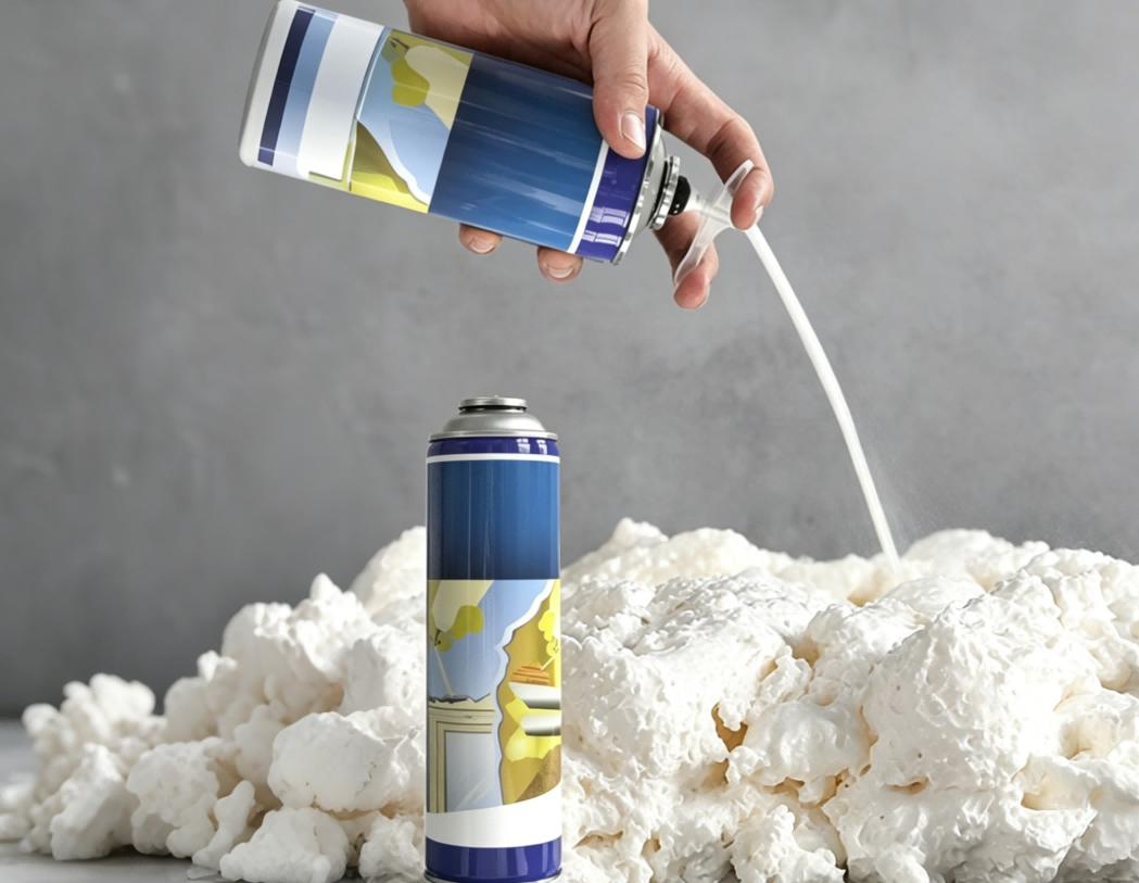
Ajustar la configuración de la recortadora a la dureza y la geometría de la suela
Shore A hardness is an indentation measurement, not a stiffness rating, and the durometer reading is only meaningful when it is taken under the specified conditions [1], [2]. That matters at the trim station because hardness changes the cutting mechanism, not just the cutting force.
Below roughly Shore A 40, polyurethane tends to smear before it cuts. The material deforms under the cutter edge and recovers behind it, leaving a torn surface rather than a chip. The fix is higher cutter speed, lower feed, and a sharp positive rake, sometimes with a blade rather than a milling cutter. Above Shore A 65, the behaviour reverses: the material chips at the edge, and the risk becomes stress marks and edge breakage rather than smearing.
| Shore A band | Cutting behaviour | Configuration note | Main risk |
|---|---|---|---|
| 30 to 40 | Smears before it cuts | High cutter speed, low feed, sharp positive rake | Torn edge and heat build-up |
| 45 to 60 | Clean chip formation | Standard rotary milling | Low, but watch cutter wear |
| 65 to 75 | Chips at the edge | Reduced feed, rigid support, climb cut | Edge chipping and stress marks |
Geometry compounds hardness. A thin sole edge deflects away from the cutter, so the fixture has to support the part within a few millimetres of the cut line. A thick wedge sole does not deflect but does load the cutter unevenly, which shows up as taper along the edge. Neither problem is solved by a more accurate machine; both are solved by fixture design.
Hardness and hardness testing are often treated as a quality department formality, but the number drives real equipment decisions. <Dureza Shore A frente a Shore D en poliuretano> covers how the two scales differ and where a reading stops being comparable.
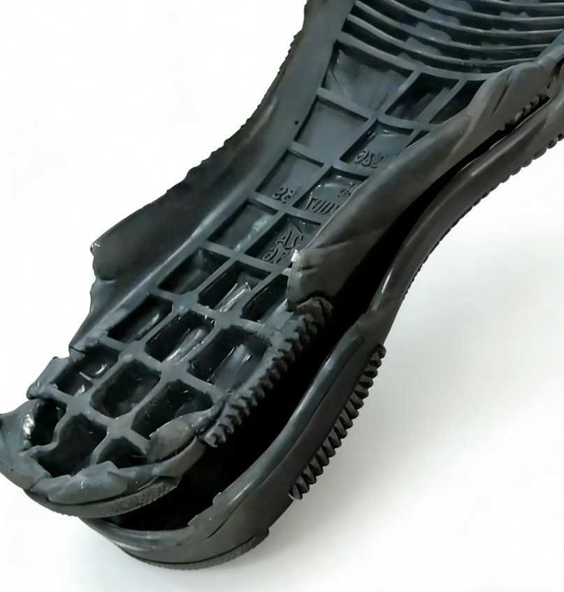
Las variables previas que determinan el rendimiento del recorte
No trimmer can hold a tolerance that the mold will not deliver. Four upstream variables account for most of the variation that reaches the trim station, and all four are cheaper to control than a machine upgrade.
Parting-line condition. A worn parting line produces a flash band that varies in thickness around the perimeter. Once that variation exceeds the trimmer’s compliance, the cutter either cuts air or digs into the sole. A flash band that varies by more than 0.3 mm around the perimeter is a mold maintenance problem, not a trimming problem.
Shot weight control. Overfill pushes material into the parting line and thickens the flash. Underfill produces short shots that cannot be trimmed at all. High-pressure metering machines typically hold component ratio within ±0.3% across the full dynamic range, which is the level of control the trim station needs to see a consistent flash.
Shot weight is the first number to check when flash thickness starts drifting between shifts. <Cómo calcular el peso de dosificación en poliuretano> covers the calculation method and the density assumptions behind it.
Demold time. Demolding too early leaves the part soft enough to deform under clamping and cutting force, and the deformation becomes a permanent dimensional error. Demolding too late makes the flash brittle, so it chips instead of cutting cleanly. Both failures look like trimming problems and neither is.
Mold temperature and release agent. Temperature sets the shrinkage that positions the trim datum. Release agent build-up changes the flash geometry shot to shot. A plant that logs both will see the correlation within a week; a plant that logs neither will keep replacing cutters.
Células de recorte en línea frente a independientes
The choice between a standalone bench-top trimmer and an inline automated cell is not a question of technology level. It is a question of volume stability, style count, and how much of the variation you have already removed.
| Criterio | Standalone bench-top | Inline automated cell |
|---|---|---|
| Annual volume | Under about 200,000 pairs | Above about 500,000 pairs |
| Style changes per shift | More than three | Fewer than one |
| Sole geometry | Complex, thin-walled, varied | Stable and repeatable |
| Labour availability | Available and trainable | Scarce or high turnover |
| Capital and floor space | Low | Alta |
| Do not choose when | Flash variation exceeds ±0.3 mm | Mold condition is unproven |
The exclusion column matters more than the others. An inline cell installed on a line with uncontrolled flash variation will run below its rated output and will be blamed for a mold problem. A bench-top trimmer installed on a stable, high-volume line will cap output within a year. Match the cell to the variation you have, not the variation you intend to have.
Elaborar la solicitud de cotización y el protocolo de aceptación
Most trimming RFQs fail because they specify a machine instead of a result. The supplier cannot design a fixture from a machine model, and the buyer cannot reject a machine that meets its own data sheet. Six fields close that gap.
| Campo de la RFQ | Qué especificar | Por qué importa |
|---|---|---|
| Sole geometry | 3D CAD plus five physical samples from different cavities | Fixture design depends on draft angle and edge radius |
| Dureza | Shore A value with the test method and condition | Cutting parameters change across the hardness band |
| Flash condition | Thickness range measured at eight perimeter points | Sets the compliance the trimmer must absorb |
| Finished tolerance | Datum, measurement method, and sample size | A tolerance without a method cannot be verified or rejected |
| Tiempo de ciclo | Seconds per pair including load and unload | Machine cycle alone understates line impact |
| Acceptance test | Sample size, run duration, and pass criteria | Prevents a hand-picked demonstration from becoming the standard |
Two further items belong in the commercial terms rather than the technical table. Changeover time should be specified in minutes with a fixture count, because the number of molds you can afford to run depends on it. Dust extraction should be specified as capture velocity at the cutter head, because polyurethane dust is both a housekeeping problem and a health exposure.

Una ruta por fases cuando la automatización total es prematura
Full inline automation is the right answer for a stable, high-volume sole program. It is the wrong first purchase for a plant still fighting flash variation, because the cell will expose every upstream weakness at once and none of them will be fixable at the trim station.
A workable sequence starts with the fixture. Adding a locating fixture and a controlled cutter speed to an existing manual station typically removes the largest part of the edge deviation for a fraction of the capital, and it proves whether the flash band is stable enough to automate. The second phase is a semi-automatic bench-top machine, which is where a unit such as the Haifeng HF-TR-M fits: pneumatic drive, ±0.1 mm trimming accuracy, a 1.1 kW alloy rotary milling cutter, a 50 to 500 mm processing range, and manual fixed positioning that suits special-shaped parts and rapid multi-model changeover without mold adjustment. The third phase is the inline cell, and it should only be entered once the first two have shown that flash thickness and shrinkage are under control.
The gate between phases is the same in each case. Run 30 consecutive parts, measure the edge deviation, and compare the spread with the tolerance you need. If the spread is still wider than the tolerance, the next phase will not fix it.
Envíe los datos de la suela antes de especificar una recortadora
Trimming automation is decided by the part, not by the machine catalogue. Tell us the sole geometry in CAD or as physical samples, the Shore A hardness with its test condition, the flash thickness range measured at eight points around the perimeter, the required finished tolerance with its measurement method, the target cycle time per pair including load and unload, the number of styles you change per shift, and the floor space available. With those seven inputs, a trimmer configuration and an acceptance protocol can be specified against your production reality rather than a demonstration part.
Haifeng Polyurethane Machinery
Info@chinahaifeng.com
WhatsApp: +86 13566296633
Preguntas frecuentes
¿Qué precisión puede alcanzar realmente el recorte automatizado de suelas de PU?
The machine’s positioning accuracy is only one term in the stack. On a well-maintained cell with a rigid fixture, production parts typically hold ±0.15 to ±0.20 mm on edge position, with flash variation and part shrinkage contributing most of the spread. If a supplier quotes ±0.05 mm on the finished sole, ask for the measurement method, the sample size, and the flash thickness range the trial ran at. A number without those three conditions cannot be compared with another supplier’s number.
¿Cuántas muestras debe usar una prueba de recorte?
At least 30 consecutive parts from a single cavity, plus five parts from each other cavity in the mold. Thirty is the minimum for a meaningful capability estimate; fewer and you are measuring luck rather than process. Take the parts across a full shift so that mold temperature drift and operator change are included. A trial that uses only parts pulled immediately after a mold clean will overstate performance and understate the maintenance interval you need.
¿Puede una misma recortadora procesar suelas de PU y de TPU?
Sometimes, but not with identical parameters. TPU is tougher and tends to chip rather than smear, so it tolerates a higher feed rate but dulls a cutter faster. PU in the Shore A 30 to 40 range smears if cutter speed is too low. A single machine can run both if it stores separate speed, feed, and depth parameters per material, and if the fixture supports the softer part without deflecting it at the cut line.
¿Qué provoca un borde deshilachado o desgarrado tras el recorte?
Three causes dominate. Cutter speed too low for the material hardness, so the edge tears instead of cutting. Feed rate too high for the flash thickness, so the cutter deflects. And a dull or chipped cutter, which is the most common and the easiest to rule out. Check cutter condition first, then speed, then feed. If the edge is fuzzy only at the toe or heel, the fixture is probably not supporting the part close enough to the cut.
¿Vale la pena el recorte en línea por debajo de 500.000 pares al año?
Usually not as a first step. Below that volume, a semi-automatic bench-top trimmer with a proper fixture and controlled cutter speed captures most of the quality gain at a fraction of the capital. The exception is a plant running few styles at high volume with stable geometry, where changeover cost is low and the labour saving compounds. The deciding number is style changes per shift, not annual volume on its own.
Referencias
[1] ISO 868, “Plastics and ebonite — Determination of indentation hardness by means of a durometer (Shore hardness),” International Organization for Standardization.
[2] ASTM D2240, “Standard Test Method for Rubber Property—Durometer Hardness,” ASTM International.
Si te interesa, echa un vistazo a estos artículos relacionados:
¿Qué es la espuma de poliuretano proyectada? Composición y aplicación
SRIM explicado: fundamentos del moldeo por inyección reactiva estructural
RRIM frente a RIM: qué proceso se adapta mejor a tu pieza estructural
Cómo calcular el peso de dosificación en poliuretano