
[مرجع سريع لمعايير عمليات Haifeng]
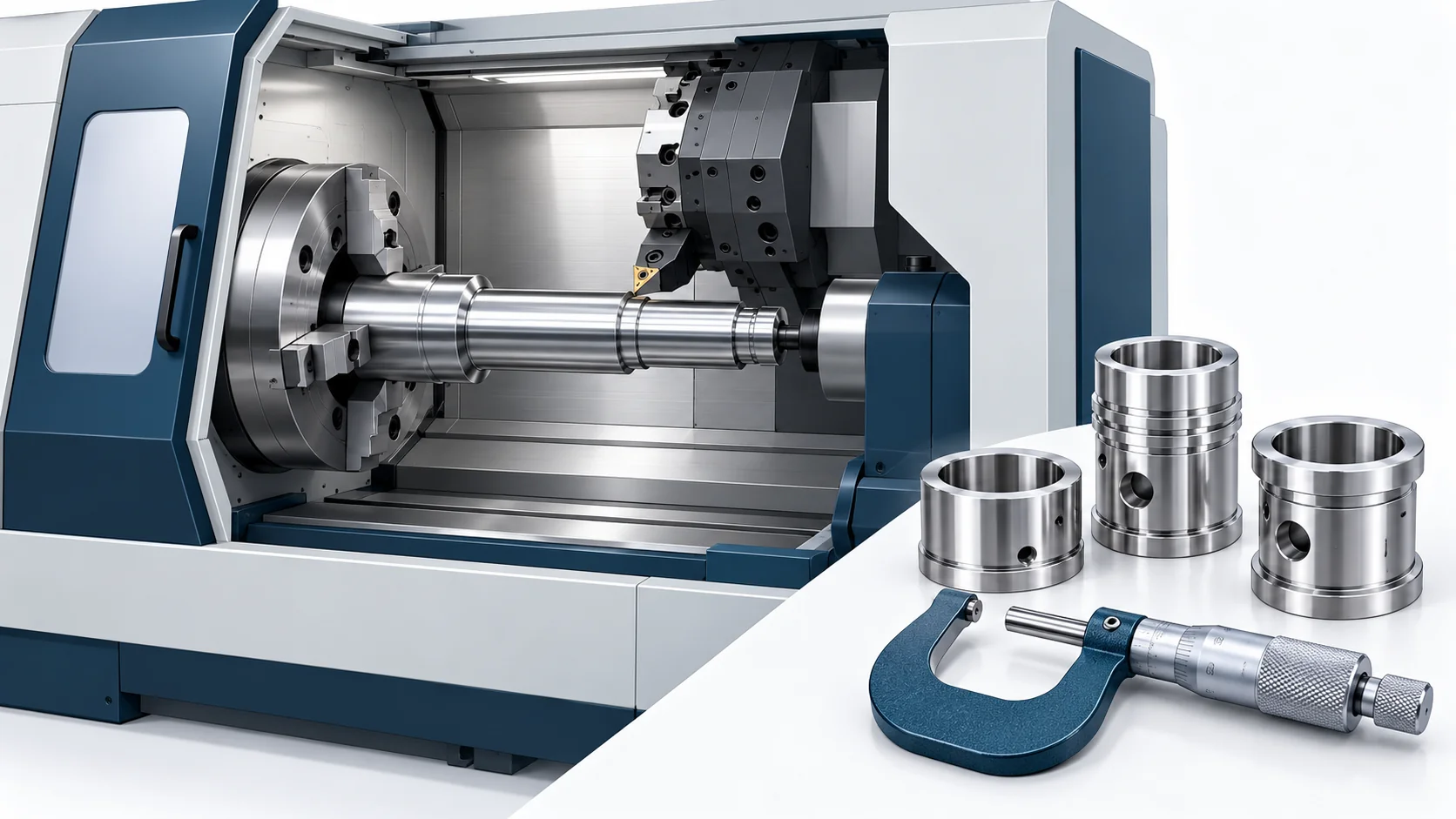
تعتمد دقة قياس الجرعات في معدات Haifeng للبولي يوريثان اعتمادًا كبيرًا على دقة الخراطة CNC للمكوّنات الدوّارة الحرجة. وكل انحراف قدره 0.005 mm في تفاوت قطر لسان مكبس مضخة القياس يمكن أن يقلل انتظام الخلوص بين المكبس وجلبة الأسطوانة بأكثر من 20%، مما يسبب تذبذبًا في معدل التدفق المقاس يتجاوز 1.5% ويهبط بدقة النسبة من ±0.3% إلى أكثر من ±0.5%. ويجب أن يكون الخلوص بين قلب صمام رأس الخلط والجلبة 0.005–0.015 mm، وأن تكون خشونة سطح الإحكام Ra ≤0.2 ميكرومتر؛ وإلا فإن التسرب الداخلي أثناء التبديل يمكن أن يخل بنسبة المواد الخام.
المعايير الرئيسية للعملية في لمحة:
| المعامل | معيار Haifeng | المرجع الصناعي | المؤشر ذو الصلة |
| دقة تحديد الموضع لمخرطة CNC | ≤±0.008 mm | ≤±0.015 mm | أداء قياس الجرعات للآلة: يُتحقق منه بشكل منفصل في ظروف اختبار متفق عليها |
| دقة تكرار تحديد الموضع | ≤±0.003 mm | ≤±0.005 mm | معامل التباين (CV) لاتساق الأجزاء في الدفعة ≤0.5% |
| الانحراف الشعاعي للمغزل | ≤0.002 mm | ≤0.003 mm | استدارة القطر الخارجي ≤0.003 mm |
| الحركة المحورية للمغزل | ≤0.002 mm | ≤0.005 مم | استواء السطح ≤0.005 mm |
| الانحراف الدائري لسطح المغزل | ≤0.002 mm | ≤0.003 mm | دقة سطح تحديد موضع الشفة |
| الخلوص العكسي | ≤0.002 mm | ≤0.005 مم | دقة الكنتور |
| تفاوت جُذَيْب مكبس مضخة قياس الجرعات | IT5–IT6 | IT6–IT7 | معامل تغاير انتظام الخلوص CV ≤10% |
| خشونة سطح تجويف صمام التحكم | Ra ≤0.2 μm | Ra ≤0.4 μm | زمن التبديل ≤0.3 ثانية؛ دون تسرب داخلي |
| خشونة سطح تجويف المكبس | Ra ≤0.4 μm | Ra ≤0.8 ميكرومتر | الكفاءة الحجمية ≥95% |
| خشونة قاع أخدود الختم | Ra ≤0.8 ميكرومتر | Ra ≤1.6 ميكرومتر | عمر مانع التسرب ≥100,000 حقنة |
| استدارة العمود | ≤0.003 mm | ≤0.005 مم | حركة انسيابية للمكبس/قلب الصمام |
| استدارية العمود | ≤0.005 مم/100 مم | ≤0.01 مم/100 مم | خلوص منتظم على طول منطقة التلاقي |
| سرعة القطع للفولاذ 316L | 120–180 م/دقيقة | 120–180 م/دقيقة | عمر الأداة ≥60 دقيقة |
| سرعة القطع لسبائك الألومنيوم | 300–800 م/دقيقة | 300–800 م/دقيقة | دقة الأبعاد IT6–IT7 |
| دقة سن اللولب لتجهيزات الأنابيب | 6H/6g | 6H/6g | لا تسريب عند 0.02 ميجاباسكال |
| درجة الحرارة المحيطة أثناء التشغيل | 20±2°م | 20±5°م | خطأ حراري ≤5 ميكرومتر |
| تكرارية المسبار داخل الماكينة | ≤0.002 mm | ≤0.005 مم | حلقة مغلقة بين التشغيل والفحص |
تُحدَّد تفاوتات المكوّنات المعنية وفق رسومات المشروع المعتمدة وإجراء الفحص. أما دقة قياس الجرعات للماكينة فتُحدَّد وتُختبر بشكل منفصل بالنسبة للتكوين المختار وحالة المادة ودرجة الحرارة والتدفق وأساس القياس؛ ولا تكفي أهداف الأبعاد للمكوّنات وحدها لإثباتها.
1. النطاق
1.1 العمليات المنطبقة
ينطبق إجراء التشغيل القياسي (SOP) هذا على الخراطة CNC لهذه الأجزاء الدوّارة الدقيقة الخاصة بمعدات Haifeng للبولي يوريثان:
| الجزء | المادة النموذجية | متطلب الدقة الرئيسي | مؤشر المعدات ذو الصلة |
| مكبس/عمود تدوير مضخة قياس الجرعات | فولاذ أدوات سبائكي/9Cr18MoV | IT5–IT6؛ Ra ≥ 0.4 ميكرومتر | الكفاءة ≥95%؛ دقة قياس الجرعات ±0.3% |
| عمود تروس مضخة قياس الجرعات | فولاذ أدوات سبائكي | IT6؛ التمحور ≤0.005 مم | تعشيق التروس والنقل السلس |
| قلب صمام رأس الخلط | 17-4PH/316L | Ra للسطح المتزاوج ≤0.2 ميكرومتر؛ الأسطوانية ≤0.003 مم | زمن التبديل ≤0.3 ثانية؛ دون تسرب داخلي |
| جلبة صمام رأس الخلط | 17-4PH/316L | تجويف IT6؛ Ra ≥ 0.2 ميكرومتر | خلوص القلب/الجلبة 0.005–0.015 مم |
| شفة محرك سيرفو | ألومنيوم 6061/7075 | استواء الوجه ≤0.01 مم؛ تفاوت التمركز IT6 | محاذاة القارنة ≤0.03 مم |
| دعامة اللولب الكروي | فولاذ سبائكي | تجويف المحمل IT6؛ التماثل المحوري ≤0.01 مم | الحركة المحورية للولب ≤0.005 مم |
| وصلة نقل المواد | 316L | سن اللولب 6H/6g؛ خشونة سطح وجه الإحكام Ra ≤0.8 ميكرومتر | لا تسريب عند 0.02 ميجاباسكال |
| حز الإحكام | 316L/فولاذ سبائكي | القاع Ra ≤0.8 ميكرومتر؛ العرض ±0.02 مم | عمر الإحكام المحدد |
| عمود إدارة منصة الصب | فولاذ سبائكي | المقعد IT6؛ الاستدارة ≤0.003 مم | تكرارية المسار ±0.05 مم |
2. التحضير قبل العمل والتحقق من دقة الماكينة
2.1 مراجعة الوثائق الفنية
| الرقم | البند | المتطلب | معيار القبول |
| 1 | برنامج الخراطة | مطابق لأحدث رسم | المراجعة مطابقة لبطاقة العملية |
| 2 | قائمة الأدوات | الطراز، والهندسة، وسجل العمر التشغيلي | قياس الانحراف وتسجيله |
| 3 | رسم التثبيت | مراجع التحديد وخطة التثبيت | دقة التحديد ≤0.005 مم |
| 4 | خطة الفحص | الأبعاد الحرجة والتفاوتات والأدوات | ISO 2768-1 أو متطلبات الرسم |
| 5 | شهادة المادة | الدرجة مطابقة للرسم | تقريرا الصلابة والتركيب مرفقان |
2.2 التحقق من دقة الماكينة
معايرة مخرطة CNC بانتظام وفق إجراء المعايرة الخاص بها. يجب ألا يتجاوز خطأ المعايرة للمعاملات الحرجة ≤0.003 مم.
| بند المعايرة | معيار Haifeng | الفترة | الأداة |
| الانحراف الشعاعي للمغزل | ≤0.002 mm | كل ثلاثة أشهر | مؤشر قرصي ومغزل معياري |
| الحركة المحورية للمغزل | ≤0.002 mm | كل ثلاثة أشهر | مؤشر قرصي |
| الانحراف الدائري لسطح المغزل | ≤0.002 mm | كل ثلاثة أشهر | مؤشر قرصي |
| دقة تحديد الموضع لمحوري X/Z | ≤±0.008 mm | كل ثلاثة أشهر | مقياس تداخل ليزري |
| تكرار تحديد الموضع لمحوري X/Z | ≤±0.003 mm | كل ثلاثة أشهر | مقياس تداخل ليزري |
| الخلوص العكسي | ≤0.002 mm | كل ثلاثة أشهر | مقياس تداخل ليزري |
| استقامة أدلة الفراشة | ≤0.01 مم/1000 مم | كل 6 أشهر | ميزان تسوية دقيق/موازي ضوئي |
| تكرار تحديد موضع البرج الدوّار | ≤±0.005 mm | شهريًا | مؤشر قرصي |
| تمركز الظرف | ≤0.01 مم | شهريًا | مغزل رئيسي ومقياس مدرج |
2.3 التحقق من دقة الأداة
تؤثر هندسة الأداة مباشرةً في دقة الأبعاد وجودة السطح. تشمل أدوات المخرطة CNC الشائعة أدوات الخراطة الخارجية، وقضبان التثقيب، وأدوات الحز، وأدوات اللولبة. يجب أن يكون التمركز الدائري الشعاعي الرئيسي لحد القطع ≤0.01 مم.
| نوع الأداة | حد التمركز | أداة الفحص | التكرار |
| أداة تشطيب خارجية | ≤0.005 مم | مقياس مدرج على كتلة V | قبل تحميل كل دفعة |
| قضيب تثقيب | ≤0.008 مم | مقياس مدرج/حلقة معايرة رئيسية | عند كل تغيير أداة |
| أداة التخديد | ≤0.01 مم | مؤشر قرصي | عند كل تغيير أداة |
| أداة اللولبة | ≤0.01 مم | مقياس مدرج/مقياس زوايا | عند كل تغيير أداة |
| أداة التشكيل | ≤0.005 مم | جهاز عرض الملامح/مجهر صانع الأدوات | عند كل تحميل |
| ارتفاع رأس الأداة بعد تركيب اللقمة | ±0.05 mm بالنسبة لمركز عمود الدوران | مقياس ارتفاع/جهاز ضبط مسبق للأدوات | عند كل تغيير أداة |
3. سير عمل منظم للخراطة CNC
3.1 التحضير قبل الوردية والإحماء
3.1.1 التأكد من حالة الماكينة
شغّل مصدر الطاقة الرئيسي، ثم ابدأ تشغيل الماكينة ونظام CNC. بعد اكتمال الفحص الذاتي دون إنذارات، أعد كل محور إلى نقطة الصفر. التسلسل الموصى به هو X ثم Z، لتأسيس نظام إحداثيات الماكينة. بعد إعادة المحاور إلى نقطة الصفر، قم بالتسخين دون حمل عند سرعة منخفضة حتى تتوزع أغشية التشحيم في محمل عمود الدوران والممرات بصورة متساوية، ويصبح تأثير التشوه الحراري على الدقة أقل.
أدنى أزمنة للتسخين:
| دقة القطعة | التسخين | الطريقة |
| عام (أقل من IT7) | ≥10 min | عمود الدوران بسرعة متوسطة دون حمل؛ تبادل حركة جميع المحاور |
| Precision (IT6–IT7) | ≥20 min | Spindle at medium/high speed unloaded; traverse all axes |
| High accuracy (IT5–IT6) | ≥30 min | Spindle unloaded at machining speed; repeatedly traverse all axes |
| Ultra-precision (IT5 or tighter) | ≥45 min | Simulate machining and monitor thermal equilibrium |
Thermal displacement accounts for approximately 40%–70% of machine-tool machining error. Lathe thermal displacement has an initial transient phase (the first three hours) and a later steady-state phase (after three hours); accuracy changes more sharply during the first phase.
3.1.2 Check coolant and lubrication systems
Check coolant level and concentration: use 8%–12% emulsion for stainless steel and 5%–8% for aluminum alloy. Check guideway lubricant and confirm the automatic lubrication system works. For precision machining, keep coolant at 20±2°C.
3.2 تثبيت قطعة العمل وإنشاء مراجع التحديد
3.2.1 Control clamping accuracy
Secure clamping directly affects machining safety and accuracy. Before clamping, clean chuck jaws and workpiece locating surfaces and remove burrs and oil.
| Clamping method | Suitable part | Locating accuracy | ملاحظات |
| Three-jaw self-centering chuck | Small/medium shafts | ≤0.02 مم | Finish-bore soft jaws to restore centering |
| Collet chuck | Precision small shafts/valve cores | ≤0.005 مم | Collet bore must match workpiece OD |
| Precision hydraulic chuck | Precision sleeves/flanges | ≤0.005 مم | Adjust force to avoid thin-wall distortion |
| Between centers with drive plate | Slim shafts/lead screws | ≤0.005 مم | Finish-grind center holes; coaxiality ≤0.002 mm |
| Dedicated mandrel fixture | Thin-wall sleeves/valve sleeves | ≤0.003 mm | Mandrel-to-bore clearance ≤0.005 mm |
3.2.2 Control tool-setting accuracy
Tool setting links the program coordinate system to the physical workpiece. Set each tool independently and enter its compensation value. Haifeng requires accuracy within ±0.003 mm. For critical parts such as metering-pump plungers and mixing-head valve cores, use a high-accuracy presetter or in-machine probe.
Select a tool-setting method:
| الطريقة | Accuracy | التطبيق |
| Manual trial cut | ±0.01 mm | General-accuracy parts |
| Optical presetter | ±0.005 mm | Precision parts |
| Automatic presetter | ±0.003 mm | High-accuracy parts |
| In-machine probe | ±0.002 mm | IT5–IT6 precision parts |
3.3 التحقق من البرنامج وقطع القطعة الأولى
3.3.1 Program simulation and dry run
Before automatic machining, use CNC graphical simulation or Dry Run mode to check for abnormal tool retraction, undefined axis movement, or possible collision with the chuck. Verify that the G codes at the beginning and end of the program (such as G90/G91 and G96/G97) match the intended operation.
3.3.2 First-article trial cut
Apply a “verify at low speed” approach to the first trial cut. Set feed override below 50% and enable Single Block mode. After machining the first feature (such as a face or OD), pause and measure critical dimensions with a micrometer or suitable gauge. Fine-tune tool compensation or work-coordinate offset if needed. Resume continuous machining at 100% override only after the part passes inspection.
3.4 معاملات القطع والتحكم في الدقة
3.4.1 Material groups and cutting parameters
CNC turning for Haifeng equipment mainly involves alloy tool steel, stainless steel (304/316L), aluminum alloy (6061/7075), and 17-4PH precipitation-hardening stainless steel.
Recommended turning parameters for 316L stainless steel (coated carbide tools):
| Operation | Cutting speed Vc (m/min) | Feed f (mm/rev) | Depth of cut ap (mm) | Tool nose radius rε (mm) |
| Roughing | 120–150 | 0.20–0.35 | 1.5–3.0 | 0.8–1.2 |
| Semi-finishing | 150–180 | 0.10–0.20 | 0.5–1.5 | 0.8 |
| التشطيب | 160–180 | 0.05–0.12 | 0.1–0.5 | 0.4–0.8 |
For stainless steel such as 316L, use 120–180 m/min to control heat and extend tool-coating life. Proper speed control lowers the risk of premature tool fracture from work hardening. Since molybdenum makes 316L more prone to work hardening than 304, use a high-feed, moderate-depth-of-cut strategy and avoid repeatedly cutting a hardened layer.
Recommended turning parameters for aluminum alloy (6061-T6/7075):
| Operation | Cutting speed Vc (m/min) | Feed f (mm/rev) | Depth of cut ap (mm) | Tool nose radius rε (mm) |
| Roughing | 300–500 | 0.25–0.45 | 1.5–4.0 | 0.8–1.2 |
| التشطيب | 500–800 | 0.05–0.15 | 0.2–0.5 | 0.4–0.8 |
The recommended cutting speed for aluminum alloy such as 6061-T6 is 300–800 m/min. With high-pressure coolant, speed can exceed 1000 m/min. An appropriate high speed can significantly reduce cycle time per part.
3.4.2 Relationship between surface roughness and feed
Feed rate directly controls surface-texture height. The theoretical roughness relationship is approximately:
Rz ≈ (f² ÷ 8rε) × 1000 (μm)
Where f = feed (mm/rev) and rε = tool nose radius (mm).
Recommended parameters by roughness requirement:
| Target roughness | Tool nose radius rε (mm) | Recommended feed f (mm/rev) | Typical part |
| Ra ≤0.2 μm | 0.4 | 0.03–0.06 | Mixing-head valve-core mating face |
| Ra ≤0.4 μm | 0.4–0.8 | 0.05–0.10 | Metering-pump plunger mating face |
| Ra ≤0.8 ميكرومتر | 0.8 | 0.08–0.15 | Seal-groove bottom |
| Ra ≤1.6 ميكرومتر | 0.8–1.2 | 0.15–0.25 | General mating face |
3.4.3 Control and compensate for thermal deformation
Thermal-deformation error is a key factor affecting CNC lathe accuracy. Apply these controls:
1. Warm up: Run the spindle unloaded at machining speed for 20–45 minutes so bearings and ball screws reach thermal equilibrium.
2. Control coolant: Maintain cutting-fluid temperature at 20±2°C to prevent heat from expanding the workpiece and tool.
3. Online compensation: Enable thermal-error compensation during long continuous operations. Systematic thermal management can reduce temperature-related machining error by more than 60%. Turning validation has shown error reductions above 75% across repeated machining and cold-start conditions.
4. Ambient temperature: Maintain the precision-machining area at 20±2°C.
3.4.4 Monitor tool wear
| Item monitored | Normal condition | Warning threshold | Response |
| Spindle load | Stable, no sharp fluctuation | Fluctuation >10% | Check tool/workpiece condition |
| Cutting sound | Even swishing sound | Shrill squeal or dull impact | Stop and check for chipped edges |
| Surface-roughness trend | Within standard | Ra increase >20% | Replace tool or adjust parameters |
| Chip shape | Regular spiral or C-shaped | Powder-like or long tangled chips | Adjust feed/speed |
| Dimensional trend | Near tolerance midpoint | One-way drift >0.005 mm | Check tool wear or thermal deformation |
3.5 الفحص داخل الماكينة والتصنيع بالحلقة المغلقة
For IT5–IT6 precision parts such as metering-pump plungers and mixing-head valve cores, use in-machine inspection for a machining-inspection closed loop. One-way probe repeatability must be ≤0.002 mm.
Procedure:
1. After semi-finishing, call the in-machine inspection program.
2. The probe automatically contacts key points (OD, bore, face, groove dimensions, etc.).
3. The system compares measurements with tolerance requirements.
4. If deviation exceeds the warning range, the system automatically corrects tool compensation.
5. Finish the part after correction and confirm final dimensions pass.
4. المعاملات الرئيسية لدقة الخراطة CNC
| الرقم | Category | المعامل | معيار Haifeng | أداة الفحص | التكرار |
| 1 | Machine | دقة تحديد الموضع لمحوري X/Z | ≤±0.008 mm | مقياس تداخل ليزري | كل ثلاثة أشهر |
| 2 | Machine | تكرار تحديد الموضع لمحوري X/Z | ≤±0.003 mm | مقياس تداخل ليزري | كل ثلاثة أشهر |
| 3 | Machine | الخلوص العكسي | ≤0.002 mm | مقياس تداخل ليزري | كل ثلاثة أشهر |
| 4 | Machine | الانحراف الشعاعي للمغزل | ≤0.002 mm | Dial indicator/master mandrel | كل ثلاثة أشهر |
| 5 | Machine | الحركة المحورية للمغزل | ≤0.002 mm | مؤشر قرصي | كل ثلاثة أشهر |
| 6 | الأداة | OD finishing-tool runout | ≤0.005 مم | مؤشر قرصي | Each batch loading |
| 7 | الأداة | Boring-bar runout | ≤0.008 مم | مقياس مدرج/حلقة معايرة رئيسية | Each tool change |
| 8 | Machining | Plunger-journal tolerance | IT5–IT6 | CMM/micrometer | First article + sampling |
| 9 | Machining | Valve-sleeve bore tolerance | IT6 | CMM/inside micrometer | First article + sampling |
| 10 | Machining | استدارة العمود | ≤0.003 mm | Roundness tester | First article + sampling |
| 11 | Machining | استدارية العمود | ≤0.005 مم/100 مم | CMM | First article + sampling |
| 12 | Machining | Stepped-shaft coaxiality | ≤0.005 مم | CMM | First article + sampling |
| 13 | Surface | خشونة سطح تجويف صمام التحكم | Ra ≤0.2 μm | Roughness tester | 100% inspection |
| 14 | Surface | خشونة سطح تجويف المكبس | Ra ≤0.4 μm | Roughness tester | 100% inspection |
| 15 | Surface | خشونة قاع أخدود الختم | Ra ≤0.8 ميكرومتر | Roughness tester | Sampling |
| 16 | Critical fit | Plunger-to-sleeve clearance | 0.005–0.015 mm | Pneumatic gauge | 100% inspection |
| 17 | Critical fit | Valve-core-to-sleeve clearance | 0.005–0.015 mm | Pneumatic gauge | 100% inspection |
| 18 | Thread | Pipeline-fitting thread | 6H/6g | Thread ring/plug gauge | First article + sampling |
| 19 | Environment | Machining temperature | 20±2°م | Temperature/humidity logger | Continuous |
| 20 | In-machine inspection | One-way probe repeatability | ≤0.002 mm | Master-ball calibration | Each shift |
5. المشكلات الشائعة ومزالق العمليات
5.1 التشوه الحراري يسبب انحرافًا أبعاديًا في الأجزاء الدقيقة
Symptom: Parts that pass in the morning show a systematic OD increase in the afternoon (typically 0.005–0.02 mm), or dimensions drift during continuous machining. Chatter or waviness appears on the turned surface, and finish is out of specification.
Root cause: Cutting and friction heat expand the lathe spindle, ball screws, and workpiece. Thermal displacement accounts for approximately 40%–70% of machine-tool error. Lathe thermal displacement has an initial transient phase (first three hours) and a steady-state phase (after three hours); accuracy changes more sharply during the first phase. Spindle axial growth can reach 0.01–0.03 mm, and ball-screw growth can reach 0.02–0.05 mm over a 1 m travel. For Haifeng parts with tolerances of only ±0.005 mm, thermal deformation is a primary cause of batch accuracy drift.
Corrective actions:
1. Warm up the spindle unloaded at machining speed for 20–45 minutes; start only after thermal equilibrium.
2. Enable thermal-error compensation during long continuous runs; systematic thermal management can reduce temperature-related error by more than 60%.
3. Schedule finishing during the stable period after the machine reaches thermal equilibrium.
4. Use a staged process for precision parts: rough machining, natural cooling, then finish machining.
5.2 تآكل الأداة يسبب انحرافًا أبعاديًا تدريجيًا
Symptom: Batch OD dimensions drift in one direction from the tolerance midpoint toward an upper or lower limit, and CV increases.
Root cause: Flank wear reduces actual depth of cut (making an OD too large or a bore too small). As the edge dulls, cutting resistance increases and dimensional deviation becomes more likely. For IT5–IT6 precision parts, every 0.01 mm increase in flank wear can cause a dimensional deviation of about 0.005–0.01 mm.
Corrective actions:
1. Maintain a tool-life log and set replacement intervals by material and cutting parameters.
2. Sample-check critical dimensions every 10–20 parts; adjust tool compensation immediately if one-way drift appears.
3. Use a new or properly reground cutting edge for precision finishing; do not use a tool that has already performed roughing.
4. For 316L, use TiAlN- or AlTiN-coated carbide tools to improve resistance to crater wear.
5.3 انحناء الأعمدة الرفيعة أثناء التشغيل
Symptom: When turning a shaft with length-to-diameter ratio above 25, the center bends, cylindricity and straightness fall out of tolerance, and chatter marks appear.
Root cause: Slim shafts have low rigidity and are prone to chatter and deformation. Radial cutting force pushes the workpiece away from the tool, reduces actual depth of cut, and makes the middle diameter too large, producing a “barrel” shape. A follower rest helps resist radial and vertical cutting forces.
Corrective actions:
1. Support the workpiece with a follower rest; fit its fingers precisely to the finished surface.
2. Use reverse turning (feed from chuck toward tailstock) so the workpiece is under axial tension rather than compression.
3. Select a tool with a 93° entering angle to generate greater axial force and lower radial force, reducing shaft deflection.
4. Use progressively lighter cuts; reduce depth gradually after roughing to release residual stress.
5. For ultra-slim shafts (L/D >50), consider ultrasonic-vibration-assisted cutting.
5.4 خشونة سطح الإحكام المفرطة تسبب تسربًا داخليًا
Symptom: Mixing-head valve-core/sleeve mating surfaces exceed Ra 0.2 μm; internal leakage during switching disrupts the raw-material ratio.
Root cause: Feed is too high or the tool nose radius is unsuitable. Roughness increases with the square of feed and decreases as nose radius increases. If finishing feed exceeds 0.10 mm/rev or nose radius is below 0.4 mm, Ra ≤0.2 μm is difficult to achieve. Worn edges or machine vibration also worsen roughness.
Corrective actions:
1. Keep finishing feed at 0.03–0.06 mm/rev and use a 0.4 mm tool nose radius.
2. Use a wiper insert to achieve better finish at higher feed.
3. If needed, add a lapping operation; lapping can reduce roughness to Ra ≤0.1 μm.
4. Inspect 100% of sealing surfaces after turning with a surface-roughness tester; nonconforming parts must not proceed.
5.5 دقة السن اللولبي غير الكافية تسبب تسربًا في الأنابيب
Symptom: Pipeline-fitting threads are too loose or tight, and the assembly fails the airtightness test (leakage at 0.02 MPa for 30 minutes).
Root cause: Thread angle, pitch, or pitch diameter is out of tolerance. Accuracy depends on machine condition, tool geometry, program accuracy, cutting parameters, material properties, and tool wear. For sealing threads, every 0.02 mm excess pitch-diameter deviation reduces contact area by about 15%, lowering sealing reliability.
Corrective actions:
1. Set the threading-tool tip slightly above workpiece center by 1% of the diameter to prevent digging in.
2. Select G32 straight infeed for high accuracy or G76 angled infeed for roughing, as appropriate.
3. Check every thread with a thread ring/plug gauge and confirm 6H/6g accuracy.
4. For sealing threads, perform both GO and NO-GO gauge checks.
5.6 تشوّه التثبيت يجعل الجلود رقيقة الجدار غير مستديرة
Symptom: Thin-wall parts such as mixing-head valve sleeves become oval or out of tolerance after machining and spring back when unclamped.
Root cause: Excessive clamping force or poorly distributed clamping points elastically deform the part while held. The tool cuts material from this deformed state; springback after unclamping shifts actual dimensions. Thinner sleeve walls are more susceptible.
Corrective actions:
1. Use a precision hydraulic chuck instead of a three-jaw chuck; its force can be adjusted and distributed evenly.
2. Use axial clamping with auxiliary radial support to avoid concentrated radial force.
3. After roughing, release the fixture and allow the part to cool naturally; then finish with lower clamping force.
4. For high-accuracy thin-wall sleeves, use a dedicated mandrel fixture with mandrel-to-bore clearance ≤0.005 mm.
5. Reduce finishing feed as appropriate (0.03–0.08 mm/rev) to limit cutting-force deformation.