
[Referencia rápida de estándares de proceso de Haifeng]
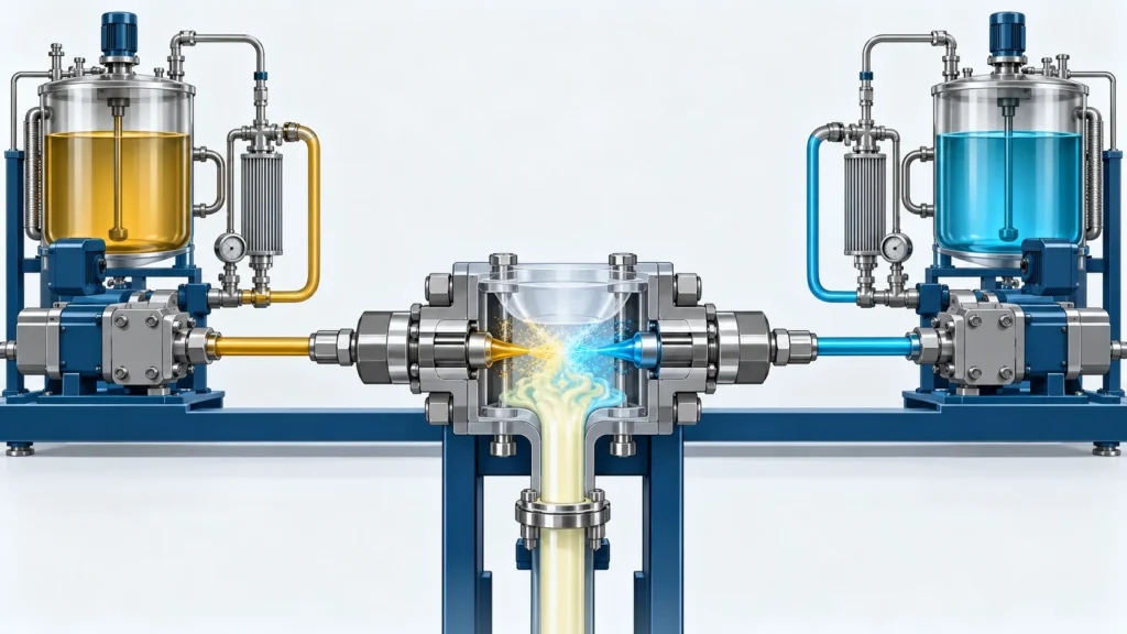
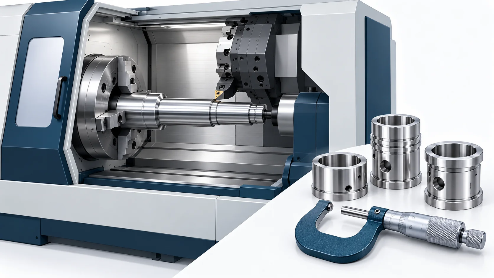
La precisión de dosificación de los equipos de poliuretano de Haifeng depende en gran medida de la precisión de torneado CNC de los componentes giratorios críticos. Cada desviación de 0,005 mm en la tolerancia del muñón del émbolo de la bomba dosificadora puede reducir la uniformidad de la holgura entre el émbolo y el manguito del cilindro en más del 20 %, lo que provoca una fluctuación del caudal dosificado superior al 1,5 % y degrada la precisión de la proporción de ±0,3 % a más de ±0,5 %. La holgura entre el obturador y el manguito del cabezal mezclador debe ser de 0,005–0,015 mm, y la rugosidad de la superficie de sellado debe ser Ra ≤0,2 μm; de lo contrario, las fugas internas durante la conmutación pueden alterar la proporción de las materias primas.
Parámetros clave del proceso de un vistazo:
| Parámetro | Estándar de Haifeng | Referencia del sector | Indicador relacionado |
| Precisión de posicionamiento del torno CNC | ≤±0,008 mm | ≤±0,015 mm | Rendimiento de dosificación de la máquina: verificar por separado en las condiciones de ensayo acordadas |
| Precisión de posicionamiento repetitivo | ≤±0,003 mm | ≤±0,005 mm | CV de consistencia de piezas por lote ≤0,5 % |
| Excentricidad radial del husillo | ≤0,002 mm | ≤0,003 mm | Redondez del diámetro exterior ≤0,003 mm |
| Movimiento axial del husillo | ≤0,002 mm | ≤0,005 mm | Planitud de la cara ≤0,005 mm |
| Excentricidad circular de la cara del husillo | ≤0,002 mm | ≤0,003 mm | Precisión de la cara de apoyo de la brida |
| Juego por inversión | ≤0,002 mm | ≤0,005 mm | Precisión del contorno |
| Tolerancia del muñón del émbolo de la bomba dosificadora | IT5–IT6 | IT6–IT7 | Uniformidad de la holgura CV ≤10 % |
| Rugosidad del ajuste del núcleo de la válvula | Ra ≤0,2 µm | Ra ≤0,4 µm | Conmutación ≤0,3 s; sin fugas internas |
| Rugosidad del ajuste del émbolo | Ra ≤0,4 µm | Ra ≤0,8 µm | Eficiencia volumétrica ≥95 % |
| Rugosidad del fondo de la ranura de sellado | Ra ≤0,8 µm | Ra ≤1,6 µm | Vida útil del sellado ≥100.000 ciclos |
| Redondez del eje | ≤0,003 mm | ≤0,005 mm | Movimiento suave del émbolo/núcleo de la válvula |
| Cilindricidad del eje | ≤0,005 mm/100 mm | ≤0,01 mm/100 mm | Holgura uniforme a lo largo de la longitud de acoplamiento |
| Velocidad de corte del 316L | 120–180 m/min | 120–180 m/min | Vida útil de la herramienta ≥60 min |
| Velocidad de corte de aleación de aluminio | 300–800 m/min | 300–800 m/min | Precisión dimensional IT6–IT7 |
| Precisión de rosca de racores de tubería | 6H/6g | 6H/6g | Sin fugas a 0,02 MPa |
| Temperatura ambiente de mecanizado | 20±2 °C | 20±5 °C | Error térmico ≤5 μm |
| Repetibilidad del palpador en máquina | ≤0,002 mm | ≤0,005 mm | Bucle cerrado mecanizado-inspección |
Las tolerancias aplicables de los componentes se definen en los planos del proyecto aprobados y en el procedimiento de inspección. La precisión de medición de la máquina se especifica y ensaya por separado para la configuración, condición del material, temperatura, caudal y base de medición seleccionados; los objetivos dimensionales de los componentes por sí solos no la establecen.
1. Alcance
1.1 Operaciones aplicables
Este SOP se aplica al torneado CNC de estas piezas rotativas de precisión para equipos de poliuretano de Haifeng:
| Pieza | Material típico | Requisito de precisión clave | Indicador del equipo relacionado |
| Émbolo/muñón de bomba dosificadora | Acero de herramientas aleado/9Cr18MoV | IT5–IT6; Ra ≤0,4 μm | Eficiencia ≥95%; precisión de dosificación ±0,3% |
| Eje engranado de bomba dosificadora | Acero de herramientas aleado | IT6; coaxialidad ≤0,005 mm | Engrane de engranajes y transmisión suave |
| Núcleo de válvula del cabezal mezclador | 17-4PH/316L | Ra de acoplamiento ≤0.2 µm; cilindricidad ≤0.003 mm | Conmutación ≤0,3 s; sin fugas internas |
| Casquillo de válvula del cabezal mezclador | 17-4PH/316L | Taladro IT6; Ra ≤0.2 µm | Juego núcleo/casquillo 0.005–0.015 mm |
| Brida del servomotor | Aluminio 6061/7075 | Planitud de cara ≤0.01 mm; centrado IT6 | Alineación del acoplamiento ≤0,03 mm |
| Soporte del husillo de bolas | Acero aleado | Taladro de rodamiento IT6; coaxialidad ≤0.01 mm | Movimiento axial del husillo ≤0,005 mm |
| Racor de transferencia de material | 316L | Rosca 6H/6g; Ra de cara de sellado ≤0.8 µm | Sin fugas a 0,02 MPa |
| Ranura de sellado | 316L/acero aleado | Ra de fondo ≤0.8 µm; ancho ±0.02 mm | Vida útil de sellado especificada |
| Eje de accionamiento de la plataforma de colada | Acero aleado | Muñón IT6; redondez ≤0.003 mm | Repetibilidad de trayectoria ±0.05 mm |
2. Preparación previa al trabajo y verificación de la precisión de la máquina
2.1 Revisión de documentos técnicos
| N.º | Elemento | Requisito | Criterio de aceptación |
| 1 | Programa de torneado | Coincide con el plano más reciente | La revisión coincide con la ficha de proceso |
| 2 | Lista de herramientas | Modelo, geometría, historial de vida útil | Excentricidad medida y registrada |
| 3 | Plano del utillaje de fijación | Referencias y plan de sujeción | Precisión de posicionamiento ≤0,005 mm |
| 4 | Plan de inspección | Dimensiones críticas, tolerancias, herramientas | ISO 2768-1 o requisitos del plano |
| 5 | Certificado de material | El grado coincide con el plano | Informes de dureza y composición incluidos |
2.2 Verificación de la precisión de la máquina
Calibre el torno CNC periódicamente conforme a su procedimiento de calibración. El error de calibración de los parámetros críticos debe ser ≤0,003 mm.
| Elemento de calibración | Estándar de Haifeng | Intervalo | Herramienta |
| Excentricidad radial del husillo | ≤0,002 mm | Trimestral | Indicador de carátula y mandril patrón |
| Movimiento axial del husillo | ≤0,002 mm | Trimestral | Indicador de carátula |
| Excentricidad circular de la cara del husillo | ≤0,002 mm | Trimestral | Indicador de carátula |
| Precisión de posicionamiento en X/Z | ≤±0,008 mm | Trimestral | Interferómetro láser |
| Repetibilidad de posicionamiento en X/Z | ≤±0,003 mm | Trimestral | Interferómetro láser |
| Juego por inversión | ≤0,002 mm | Trimestral | Interferómetro láser |
| Rectitud de la guía del bancada | ≤0,01 mm/1000 mm | Cada 6 meses | Nivel de precisión/colimador |
| Repetibilidad de posicionamiento del revólver | ≤±0,005 mm | Mensual | Indicador de carátula |
| Centrado del plato | ≤0,01 mm | Mensual | Mandril maestro y comparador de carátula |
2.3 Verificación de la precisión de las herramientas
La geometría de la herramienta afecta directamente a la precisión dimensional y a la calidad superficial. Las herramientas habituales del torno CNC incluyen herramientas de torneado exterior, barras de mandrinar, herramientas de ranurado y herramientas de roscado. La excentricidad circular radial del filo principal debe ser ≤0,01 mm.
| Tipo de herramienta | Límite de excentricidad | Herramienta de inspección | Frecuencia |
| Herramienta de acabado para diámetro exterior | ≤0,005 mm | Indicador de carátula sobre bloque en V | Before loading each batch |
| Barra de mandrinar | ≤0.008 mm | Indicador de carátula/anillo de calibración patrón | Every tool change |
| Herramienta de ranurado | ≤0,01 mm | Indicador de carátula | Every tool change |
| Herramienta de roscado | ≤0,01 mm | Indicador de carátula/medidor de ángulos | Every tool change |
| Herramienta de perfil | ≤0,005 mm | Proyector de perfiles/microscopio de taller | En cada carga |
| Altura de la punta de la herramienta tras la instalación del inserto | ±0,05 mm respecto al centro del husillo | Medidor de altura/presetter de herramientas | Every tool change |
3. Flujo de trabajo estructurado de torneado CNC
3.1 Preparación previa al turno y calentamiento
3.1.1 Confirm machine status
Conecte la alimentación principal, luego arranque la máquina y el sistema CNC. Una vez completada la autocomprobación sin alarmas, lleve cada eje a su posición de origen. La secuencia recomendada es X y luego Z, para establecer el sistema de coordenadas de la máquina. Tras el retorno de origen, realice un calentamiento sin carga a baja velocidad para que las películas de lubricante de los rodamientos del husillo y de las guías se distribuyan uniformemente y la deformación térmica afecte menos a la precisión.
Tiempos mínimos de calentamiento:
| Precisión de la pieza | Calentamiento | Método |
| General (below IT7) | ≥10 min | Spindle at medium speed unloaded; reciprocate all axes |
| Precision (IT6–IT7) | ≥20 min | Spindle at medium/high speed unloaded; traverse all axes |
| High accuracy (IT5–IT6) | ≥30 min | Spindle unloaded at machining speed; repeatedly traverse all axes |
| Ultra-precision (IT5 or tighter) | ≥45 min | Simulate machining and monitor thermal equilibrium |
Thermal displacement accounts for approximately 40%–70% of machine-tool machining error. Lathe thermal displacement has an initial transient phase (the first three hours) and a later steady-state phase (after three hours); accuracy changes more sharply during the first phase.
3.1.2 Check coolant and lubrication systems
Check coolant level and concentration: use 8%–12% emulsion for stainless steel and 5%–8% for aluminum alloy. Check guideway lubricant and confirm the automatic lubrication system works. For precision machining, keep coolant at 20±2°C.
3.2 Sujeción de la pieza y establecimiento de referencias
3.2.1 Control clamping accuracy
Secure clamping directly affects machining safety and accuracy. Before clamping, clean chuck jaws and workpiece locating surfaces and remove burrs and oil.
| Clamping method | Suitable part | Locating accuracy | Notes |
| Three-jaw self-centering chuck | Small/medium shafts | ≤0,02 mm | Finish-bore soft jaws to restore centering |
| Collet chuck | Precision small shafts/valve cores | ≤0,005 mm | Collet bore must match workpiece OD |
| Precision hydraulic chuck | Precision sleeves/flanges | ≤0,005 mm | Adjust force to avoid thin-wall distortion |
| Between centers with drive plate | Slim shafts/lead screws | ≤0,005 mm | Finish-grind center holes; coaxiality ≤0.002 mm |
| Dedicated mandrel fixture | Thin-wall sleeves/valve sleeves | ≤0,003 mm | Mandrel-to-bore clearance ≤0.005 mm |
3.2.2 Control tool-setting accuracy
Tool setting links the program coordinate system to the physical workpiece. Set each tool independently and enter its compensation value. Haifeng requires accuracy within ±0.003 mm. For critical parts such as metering-pump plungers and mixing-head valve cores, use a high-accuracy presetter or in-machine probe.
Select a tool-setting method:
| Método | Accuracy | Aplicación |
| Manual trial cut | ±0.01 mm | General-accuracy parts |
| Optical presetter | ±0.005 mm | Precision parts |
| Automatic presetter | ±0.003 mm | High-accuracy parts |
| In-machine probe | ±0.002 mm | IT5–IT6 precision parts |
3.3 Validación del programa y corte de la primera pieza
3.3.1 Program simulation and dry run
Before automatic machining, use CNC graphical simulation or Dry Run mode to check for abnormal tool retraction, undefined axis movement, or possible collision with the chuck. Verify that the G codes at the beginning and end of the program (such as G90/G91 and G96/G97) match the intended operation.
3.3.2 First-article trial cut
Apply a “verify at low speed” approach to the first trial cut. Set feed override below 50% and enable Single Block mode. After machining the first feature (such as a face or OD), pause and measure critical dimensions with a micrometer or suitable gauge. Fine-tune tool compensation or work-coordinate offset if needed. Resume continuous machining at 100% override only after the part passes inspection.
3.4 Parámetros de corte y control de precisión
3.4.1 Material groups and cutting parameters
CNC turning for Haifeng equipment mainly involves alloy tool steel, stainless steel (304/316L), aluminum alloy (6061/7075), and 17-4PH precipitation-hardening stainless steel.
Recommended turning parameters for 316L stainless steel (coated carbide tools):
| Operation | Cutting speed Vc (m/min) | Feed f (mm/rev) | Depth of cut ap (mm) | Tool nose radius rε (mm) |
| Roughing | 120–150 | 0.20–0.35 | 1.5–3.0 | 0.8–1.2 |
| Semi-finishing | 150–180 | 0.10–0.20 | 0.5–1.5 | 0.8 |
| Finishing | 160–180 | 0.05–0.12 | 0.1–0.5 | 0.4–0.8 |
For stainless steel such as 316L, use 120–180 m/min to control heat and extend tool-coating life. Proper speed control lowers the risk of premature tool fracture from work hardening. Since molybdenum makes 316L more prone to work hardening than 304, use a high-feed, moderate-depth-of-cut strategy and avoid repeatedly cutting a hardened layer.
Recommended turning parameters for aluminum alloy (6061-T6/7075):
| Operation | Cutting speed Vc (m/min) | Feed f (mm/rev) | Depth of cut ap (mm) | Tool nose radius rε (mm) |
| Roughing | 300–500 | 0.25–0.45 | 1.5–4.0 | 0.8–1.2 |
| Finishing | 500–800 | 0.05–0.15 | 0.2–0.5 | 0.4–0.8 |
The recommended cutting speed for aluminum alloy such as 6061-T6 is 300–800 m/min. With high-pressure coolant, speed can exceed 1000 m/min. An appropriate high speed can significantly reduce cycle time per part.
3.4.2 Relationship between surface roughness and feed
Feed rate directly controls surface-texture height. The theoretical roughness relationship is approximately:
Rz ≈ (f² ÷ 8rε) × 1000 (μm)
Where f = feed (mm/rev) and rε = tool nose radius (mm).
Recommended parameters by roughness requirement:
| Target roughness | Tool nose radius rε (mm) | Recommended feed f (mm/rev) | Typical part |
| Ra ≤0,2 µm | 0.4 | 0.03–0.06 | Mixing-head valve-core mating face |
| Ra ≤0,4 µm | 0.4–0.8 | 0.05–0.10 | Metering-pump plunger mating face |
| Ra ≤0,8 µm | 0.8 | 0.08–0.15 | Seal-groove bottom |
| Ra ≤1,6 µm | 0.8–1.2 | 0.15–0.25 | General mating face |
3.4.3 Control and compensate for thermal deformation
Thermal-deformation error is a key factor affecting CNC lathe accuracy. Apply these controls:
1. Warm up: Run the spindle unloaded at machining speed for 20–45 minutes so bearings and ball screws reach thermal equilibrium.
2. Control coolant: Maintain cutting-fluid temperature at 20±2°C to prevent heat from expanding the workpiece and tool.
3. Online compensation: Enable thermal-error compensation during long continuous operations. Systematic thermal management can reduce temperature-related machining error by more than 60%. Turning validation has shown error reductions above 75% across repeated machining and cold-start conditions.
4. Ambient temperature: Maintain the precision-machining area at 20±2°C.
3.4.4 Monitor tool wear
| Item monitored | Normal condition | Warning threshold | Response |
| Spindle load | Stable, no sharp fluctuation | Fluctuation >10% | Check tool/workpiece condition |
| Cutting sound | Even swishing sound | Shrill squeal or dull impact | Stop and check for chipped edges |
| Surface-roughness trend | Within standard | Ra increase >20% | Replace tool or adjust parameters |
| Chip shape | Regular spiral or C-shaped | Powder-like or long tangled chips | Adjust feed/speed |
| Dimensional trend | Near tolerance midpoint | One-way drift >0.005 mm | Check tool wear or thermal deformation |
3.5 Inspección en máquina y mecanizado en circuito cerrado
For IT5–IT6 precision parts such as metering-pump plungers and mixing-head valve cores, use in-machine inspection for a machining-inspection closed loop. One-way probe repeatability must be ≤0.002 mm.
Procedure:
1. After semi-finishing, call the in-machine inspection program.
2. The probe automatically contacts key points (OD, bore, face, groove dimensions, etc.).
3. The system compares measurements with tolerance requirements.
4. If deviation exceeds the warning range, the system automatically corrects tool compensation.
5. Finish the part after correction and confirm final dimensions pass.
4. Parámetros clave para la precisión del torneado CNC
| N.º | Category | Parámetro | Estándar de Haifeng | Herramienta de inspección | Frecuencia |
| 1 | Machine | Precisión de posicionamiento en X/Z | ≤±0,008 mm | Interferómetro láser | Trimestral |
| 2 | Machine | Repetibilidad de posicionamiento en X/Z | ≤±0,003 mm | Interferómetro láser | Trimestral |
| 3 | Machine | Juego por inversión | ≤0,002 mm | Interferómetro láser | Trimestral |
| 4 | Machine | Excentricidad radial del husillo | ≤0,002 mm | Dial indicator/master mandrel | Trimestral |
| 5 | Machine | Movimiento axial del husillo | ≤0,002 mm | Indicador de carátula | Trimestral |
| 6 | Herramienta | OD finishing-tool runout | ≤0,005 mm | Indicador de carátula | Each batch loading |
| 7 | Herramienta | Boring-bar runout | ≤0.008 mm | Indicador de carátula/anillo de calibración patrón | Each tool change |
| 8 | Machining | Plunger-journal tolerance | IT5–IT6 | CMM/micrometer | First article + sampling |
| 9 | Machining | Valve-sleeve bore tolerance | IT6 | CMM/inside micrometer | First article + sampling |
| 10 | Machining | Redondez del eje | ≤0,003 mm | Roundness tester | First article + sampling |
| 11 | Machining | Cilindricidad del eje | ≤0,005 mm/100 mm | CMM | First article + sampling |
| 12 | Machining | Stepped-shaft coaxiality | ≤0,005 mm | CMM | First article + sampling |
| 13 | Surface | Rugosidad del ajuste del núcleo de la válvula | Ra ≤0,2 µm | Roughness tester | 100% inspection |
| 14 | Surface | Rugosidad del ajuste del émbolo | Ra ≤0,4 µm | Roughness tester | 100% inspection |
| 15 | Surface | Rugosidad del fondo de la ranura de sellado | Ra ≤0,8 µm | Roughness tester | Sampling |
| 16 | Critical fit | Plunger-to-sleeve clearance | 0.005–0.015 mm | Pneumatic gauge | 100% inspection |
| 17 | Critical fit | Valve-core-to-sleeve clearance | 0.005–0.015 mm | Pneumatic gauge | 100% inspection |
| 18 | Thread | Pipeline-fitting thread | 6H/6g | Thread ring/plug gauge | First article + sampling |
| 19 | Environment | Machining temperature | 20±2 °C | Temperature/humidity logger | Continua |
| 20 | In-machine inspection | One-way probe repeatability | ≤0,002 mm | Master-ball calibration | Each shift |
5. Problemas comunes y riesgos del proceso
5.1 La deformación térmica provoca la deriva dimensional de las piezas de precisión
Symptom: Parts that pass in the morning show a systematic OD increase in the afternoon (typically 0.005–0.02 mm), or dimensions drift during continuous machining. Chatter or waviness appears on the turned surface, and finish is out of specification.
Root cause: Cutting and friction heat expand the lathe spindle, ball screws, and workpiece. Thermal displacement accounts for approximately 40%–70% of machine-tool error. Lathe thermal displacement has an initial transient phase (first three hours) and a steady-state phase (after three hours); accuracy changes more sharply during the first phase. Spindle axial growth can reach 0.01–0.03 mm, and ball-screw growth can reach 0.02–0.05 mm over a 1 m travel. For Haifeng parts with tolerances of only ±0.005 mm, thermal deformation is a primary cause of batch accuracy drift.
Corrective actions:
1. Warm up the spindle unloaded at machining speed for 20–45 minutes; start only after thermal equilibrium.
2. Enable thermal-error compensation during long continuous runs; systematic thermal management can reduce temperature-related error by more than 60%.
3. Schedule finishing during the stable period after the machine reaches thermal equilibrium.
4. Use a staged process for precision parts: rough machining, natural cooling, then finish machining.
5.2 El desgaste de la herramienta provoca una deriva dimensional gradual
Symptom: Batch OD dimensions drift in one direction from the tolerance midpoint toward an upper or lower limit, and CV increases.
Root cause: Flank wear reduces actual depth of cut (making an OD too large or a bore too small). As the edge dulls, cutting resistance increases and dimensional deviation becomes more likely. For IT5–IT6 precision parts, every 0.01 mm increase in flank wear can cause a dimensional deviation of about 0.005–0.01 mm.
Corrective actions:
1. Maintain a tool-life log and set replacement intervals by material and cutting parameters.
2. Sample-check critical dimensions every 10–20 parts; adjust tool compensation immediately if one-way drift appears.
3. Use a new or properly reground cutting edge for precision finishing; do not use a tool that has already performed roughing.
4. For 316L, use TiAlN- or AlTiN-coated carbide tools to improve resistance to crater wear.
5.3 Los ejes esbeltos se flexionan durante el mecanizado
Symptom: When turning a shaft with length-to-diameter ratio above 25, the center bends, cylindricity and straightness fall out of tolerance, and chatter marks appear.
Root cause: Slim shafts have low rigidity and are prone to chatter and deformation. Radial cutting force pushes the workpiece away from the tool, reduces actual depth of cut, and makes the middle diameter too large, producing a “barrel” shape. A follower rest helps resist radial and vertical cutting forces.
Corrective actions:
1. Support the workpiece with a follower rest; fit its fingers precisely to the finished surface.
2. Use reverse turning (feed from chuck toward tailstock) so the workpiece is under axial tension rather than compression.
3. Select a tool with a 93° entering angle to generate greater axial force and lower radial force, reducing shaft deflection.
4. Use progressively lighter cuts; reduce depth gradually after roughing to release residual stress.
5. For ultra-slim shafts (L/D >50), consider ultrasonic-vibration-assisted cutting.
5.4 Una rugosidad excesiva de la superficie de sellado provoca fugas internas
Symptom: Mixing-head valve-core/sleeve mating surfaces exceed Ra 0.2 μm; internal leakage during switching disrupts the raw-material ratio.
Root cause: Feed is too high or the tool nose radius is unsuitable. Roughness increases with the square of feed and decreases as nose radius increases. If finishing feed exceeds 0.10 mm/rev or nose radius is below 0.4 mm, Ra ≤0.2 μm is difficult to achieve. Worn edges or machine vibration also worsen roughness.
Corrective actions:
1. Keep finishing feed at 0.03–0.06 mm/rev and use a 0.4 mm tool nose radius.
2. Use a wiper insert to achieve better finish at higher feed.
3. If needed, add a lapping operation; lapping can reduce roughness to Ra ≤0.1 μm.
4. Inspect 100% of sealing surfaces after turning with a surface-roughness tester; nonconforming parts must not proceed.
5.5 Una precisión de rosca insuficiente provoca fugas en la tubería
Symptom: Pipeline-fitting threads are too loose or tight, and the assembly fails the airtightness test (leakage at 0.02 MPa for 30 minutes).
Root cause: Thread angle, pitch, or pitch diameter is out of tolerance. Accuracy depends on machine condition, tool geometry, program accuracy, cutting parameters, material properties, and tool wear. For sealing threads, every 0.02 mm excess pitch-diameter deviation reduces contact area by about 15%, lowering sealing reliability.
Corrective actions:
1. Set the threading-tool tip slightly above workpiece center by 1% of the diameter to prevent digging in.
2. Select G32 straight infeed for high accuracy or G76 angled infeed for roughing, as appropriate.
3. Check every thread with a thread ring/plug gauge and confirm 6H/6g accuracy.
4. For sealing threads, perform both GO and NO-GO gauge checks.
5.6 La deformación por sujeción hace que los manguitos de pared fina pierdan la redondez
Symptom: Thin-wall parts such as mixing-head valve sleeves become oval or out of tolerance after machining and spring back when unclamped.
Root cause: Excessive clamping force or poorly distributed clamping points elastically deform the part while held. The tool cuts material from this deformed state; springback after unclamping shifts actual dimensions. Thinner sleeve walls are more susceptible.
Corrective actions:
1. Use a precision hydraulic chuck instead of a three-jaw chuck; its force can be adjusted and distributed evenly.
2. Use axial clamping with auxiliary radial support to avoid concentrated radial force.
3. After roughing, release the fixture and allow the part to cool naturally; then finish with lower clamping force.
4. For high-accuracy thin-wall sleeves, use a dedicated mandrel fixture with mandrel-to-bore clearance ≤0.005 mm.
5. Reduce finishing feed as appropriate (0.03–0.08 mm/rev) to limit cutting-force deformation.