
Dashboard back-foaming fails most often at the two surfaces that should contain the shot: the preformed skin and the fixture that supports it. The metering machine gets attention, but the skin-to-substrate cavity and the seal land decide whether the foam fills cleanly or escapes into a visible Class A edge. The practical task is to make the cavity boundary predictable before changing chemistry or pour rate. That requires looking at skin thickness variation, insert seating, clamp deflection, vent area, and shot weight together, because each one changes the pressure the other sees.
Para conocer la ruta de producción más amplia y las interfaces del equipo, consulte nuestros automotive PU manufacturing systems.
How the Skin Changes the Back-Foam Cavity
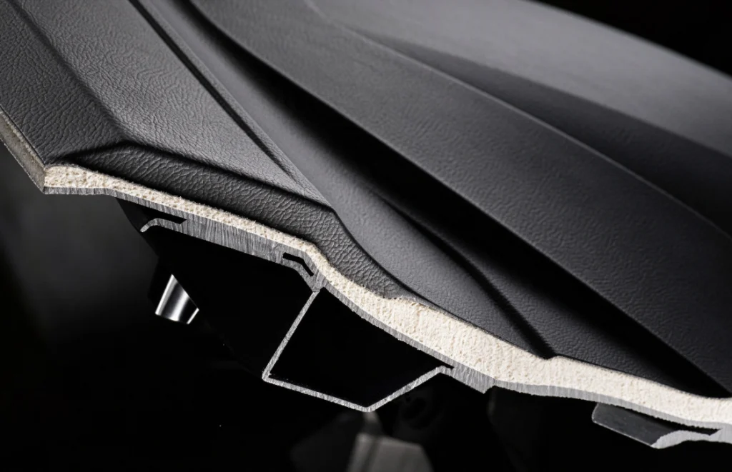
The skin is not a passive cover. Its thickness, temperature, and surface condition change the cavity volume and the flow path. A preformed skin thins out at radii and grain texture, so the same shot weight can overfill a flat area while leaving a low spot at a deep draw. If the skin enters the fixture below the process temperature, the first foam to contact it chills and forms a denser boundary layer instead of flowing along the surface. If the skin carries residual release agent or finger oil, the backing may not bond where the part needs cohesive failure during a burst test. Establish the skin side of the interface first: map thickness at the pour entry, the far corners, and the clip bosses, and record the preheat or conditioning step before setting the machine recipe.
To coordinate the skin, fixture and material-delivery package, review the dashboard PU backfoaming solution.
The backing layer is usually a semi-rigid foam formulated for gap filling and energy absorption. Its role is to fill the space between the skin and the structural substrate without telegraphing through the show surface. That only works when the skin stays at the same position the cavity model assumed. A skin that shifts during loading changes the true fill volume more than a small ratio adjustment can correct.

Fixture Sealing and Clamping Interfaces
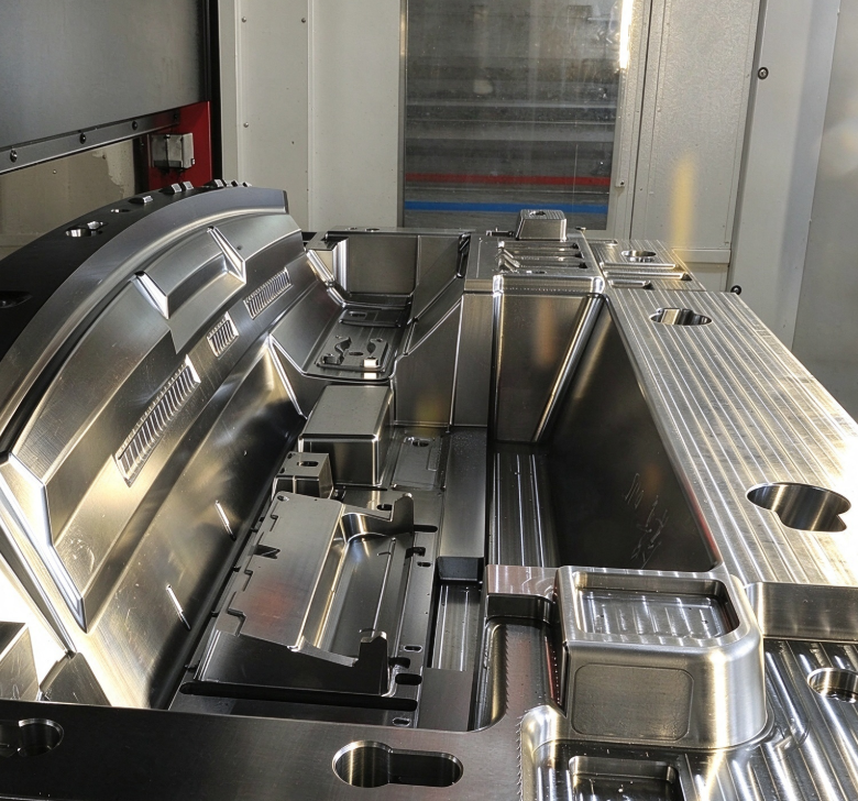
Fixture leaks are usually misinterpreted as metering or chemistry problems. Foam follows the path of least resistance, and an open seal land offers a lower resistance path than a long cavity. The fixture must hold the skin edge against a continuous seal face, not just close the mold. If the edge land is filled with flash or worn past its witness mark, the clamp tonnage no longer predicts what happens at the seal. Inserts such as clips, brackets, and wiring channels need a hard stop: when an insert floats, the shot pushes it backward and creates a short fill or a visible sink behind the boss.
| Interface point | What to inspect | What the defect pattern tells you |
|---|---|---|
| Skin edge land | Seal groove depth, flash accumulation, full-perimeter witness mark | Edge leak, skin marking, or clamp drift |
| Insert bosses | Boss height vs cavity, insert seated against a hard stop, retained hardware | Short fill around the boss, insert shift, or backside sink |
| Vent channel | Clean cross-section, no foam dust, no closed flash | High back-pressure, density streaks, or uncontrolled weep |
| Fixture face temperature | Water circuit flow, cold spots, surface thermocouple reading | Chilled skin, voids, or slow rise at one corner |
| Clamp repeatability | Closed-gap measurement, pressure trend, witness mark consistency | Part-to-part density shift or edge blowout |
The fixture also loads the skin. If the loading fixture stretches a deep-draw area when the mold closes, the skin may rebound after demolding and pull the foam surface into a low spot. Check the loaded skin with the same reference points used in the CAD cavity model. A fixture that changes the skin shape changes the effective cavity volume that the shot calculation assumed.
Shot Weight and Fill Path Planning
Shot weight should be calculated from the effective cavity volume, not copied from a previous part with a similar-looking mold. The target shot equals cavity volume times molded density times an overpack factor, but two of those values move. The skin deflection and the insert seating change the true volume, and the molded density changes with vent restriction and pack. Use the machine’s flow control to split the pour into the low-area entry and a short second position at the last-fill corner when the cavity has a steep draw. More shot adds plan view area and leak pressure instead of filling the starved region.
A dashboard cavity changes as the skin deflects and the substrate shifts under foam pressure. <Cómo calcular el peso de dosificación en poliuretano> covers how to turn final part volume and molded density into a repeatable shot weight instead of relying on a machine default.
The fill path should start in the deepest area and finish at the vented high point. If the mix head moves across the cavity, the path becomes a series of pressure sources rather than one front. That makes last-fill detection unreliable and can trap air at a mid-cavity rib.
Venting and Skin Distortion During Rise
Vent area sets the pressure the skin and seals actually see. A vent that is too small turns the rise into a compression stage, pushing the skin outward and forcing material along the edge. A vent that is too large lets the foam weep before it reaches the outer seal, creating flash and a lean edge. The useful range is found by keeping the vent open during the flow stage and letting the cream line reach the last vent before the gel reaction builds pressure. If the skin shows a polished mark at the vent, the local pressure is too high. If the foam reaches the vent as a bubble, the path is not filled.
Pressure that cannot escape through a small vent pushes back on the skin and can leave a dense surface or a visible mark after cure. <El papel del tiempo de subida en el espumado de poliuretano> covers how rise time, gel time, and vent timing combine to set the fill pattern.
After demolding, the backing continues to cool and the polymer network can contract unevenly where the skin is thin or the pack is high. That is why a part that looks full at demold can show a shallow dish or edge lift after cooling. Hold the part in the fixture or a cooling jig until the surface is stable if the geometry is flat and visible, and compare a cut section from the pour entry, the high point, and the last vent before accepting a density target.
Skin distortion and edge lift can also appear after demolding as the foam cools and the backing shrinks. <Causas de la contracción en la espuma de poliuretano y cómo controlarla> covers the cure and formulation factors that change dimensional stability across the part.

Acceptance Checks Before Releasing the Cell
Release the cell only after the interface checks are observable, not after a few good consecutive parts. Run a short-shot sequence first: stop at roughly 30 to 40 percent fill and confirm the flow reaches the intended low corner before the cream line closes. Then run a full shot and record the clamp gap, vent weep length, skin surface temperature, and demold time. Cut one part through the pour entry and one through the last-fill corner to compare cell structure and density gradient. Finally, check the backside of every insert and clip location for witness marks that match the fixture stops.
- Confirm the short-shot path reaches the last-fill corner without skin lift.
- Record full-shot clamp gap, vent weep length, and demold time.
- Cut sections at the pour entry and last-fill area to compare density.
- Verify witness marks at insert and skin edge locations.
Define the Dashboard Interface Before Ordering
Send the interface data you already have: skin material and thickness map, substrate and boss locations, target shot weight or cavity volume, and photos of the edge leak or distortion point. Haifeng Polyurethane Machinery can turn those inputs into a trial scope for the metering, mix head, and fixture interfaces. Contact Info@chinahaifeng.com or WhatsApp +86 13566296633.
Preguntas frecuentes
How is dashboard back-foaming different from ordinary foam molding?
The main difference is the visible skin. In ordinary foam molding, the cavity wall is usually a rigid mold face that sets the surface. In dashboard back-foaming, the skin is part of the cavity boundary and deflects under foam pressure, so fill, vent, and clamp settings all affect the show surface. The backing must also bond to the skin without letting the foam mark through. That changes the acceptable shot weight window and makes fixture seal condition a first-order variable.
Does the skin need preheating before the shot?
Not always, but the skin temperature at the shot start must be stable and above the point where the foam chills into a dense boundary layer. The required preheat depends on the skin material, thickness, and the foam system’s cream time. A thin soft skin loses heat faster than a thick preformed panel, so the fixture face temperature can be as important as the oven setting. Record the skin surface temperature at the last-fill corner, not only at the pour entry.
Why does foam still leak at the skin edge when the fixture closes tightly?
Because foam pressure is lower at the flow front and rises only after the cavity fills, a fixture can hold the edge during the initial flow and still open locally when the gel reaction builds pressure. Leakage points to the seal land condition, the vent area, or a changing cavity volume from skin stretch or insert shift, not just clamp force. Check the witness marks, remove flash, and verify the last vent sees the cream line before final pressure rise.
What belongs in the first trial report?
The report should connect machine settings to part evidence. Include the shot weight, flow path positions, component ratio, fixture temperature, clamp gap, vent weep length, demold time, and a cut-section map from the pour entry to the last-fill area. Add photos of the skin surface at the vents and every insert location. That makes the next trial a controlled adjustment instead of another guess.
Si te interesa, echa un vistazo a estos artículos relacionados:
¿Qué es la espuma de poliuretano proyectada? Composición y aplicación
SRIM explicado: fundamentos del moldeo por inyección reactiva estructural