
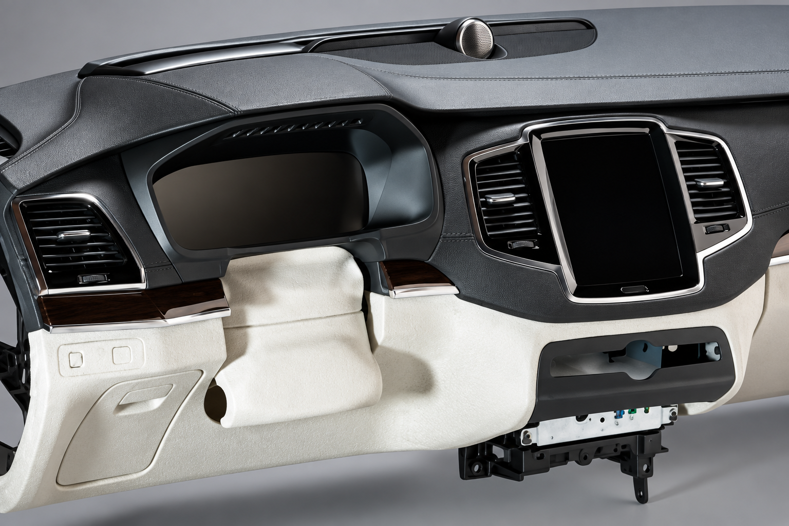
حل الرغوة الخلفية بتقنية PU للوحات عدادات السيارات
Configure high-pressure polyurethane backfoaming around the prepared skin, substrate or carrier, mold cavity and selected formulation. Production workcells and technical-center systems use different output, handling and validation requirements. The foam process and finished instrument-panel qualification are defined for the actual assembly.
PU Backfoaming for Instrument Panels and R&D Samples
Configure high-pressure polyurethane backfoaming around the prepared skin, substrate or carrier, mold cavity and selected formulation. Production workcells and technical-center systems use different output, handling and validation requirements. The foam process and finished instrument-panel qualification are defined for the actual assembly.
Material and Tooling Scope
Review the selected skin, carrier construction, cavity geometry, vents, formulation and mold temperature together. Filling quality, adhesion and surface appearance require representative trials and the agreed inspection method.
Production and Technical-Center Routes
A production workcell is configured around the manufacturing schedule. A technical-center system supports formulation changes, comparative tests and sample tooling. The two routes do not share a universal output or demolding-time guarantee.
Identify whether the request is for production backfoaming or a development center. Production needs defined skin/substrate handling and mold residence; development work needs the intended material trials, head selection and measurement capability. Existing technical illustrations describe their stated reference assemblies.
Automotive Dashboard Backfoaming Workflow
Define the sequence for the selected production or sample tool. Carrier movements, injection duration and foam cure are separate stages.
Condition and select the materials
Prepare A polyol and B isocyanate at the approved temperatures, select the recipe and verify component discharge and ratio under the agreed conditions.
Prepare the skin and tooling
Clean and prepare the tool, apply the approved release system and position the skin/carrier. Select the fixture, venting and optional tilt movements for the drawing.
Meter and inject
Use the configured high-pressure impingement head and injection program. Coordinate head access, pressure build-up, shot size and the approved mold state.
المواصفات الهندسية والمعلمات الفنية
Use the applicable configuration reference. Earlier production/carrier references and the technical-center system below are separate packages; the approved proposal selects the equipment and acceptance conditions.
Backfoaming Selection Inputs
| مجال الاختيار | Required inputs |
|---|---|
| Part construction | Prepared skin, carrier/substrate, cavity thickness, vents, appearance and adhesion requirements. |
| المادة | Polyol/isocyanate data, ratio, viscosity at process temperature and reaction/cure window. |
| وضع التشغيل | Production schedule or R&D/sample workflow, shot size, head access and changeover frequency. |
| Validation | Component discharge/ratio checks, representative filling trials, part inspection and separate assembly qualification. |
Separate Production Metering and Electric-Carrier Reference
The following reference package supplements this dashboard backfoaming solution. It combines high-pressure metering with an optional electric mold carrier, mold identification, stored movement recipes and material-supply interfaces. These values describe one configuration and are separate from broader machine-family or part-performance values above.
| المعامل | التكوين المرجعي | Selection notes |
|---|---|---|
| Specific Instrument-Panel Metering Output | 80–320 g/s (4.8–19.2 kg/min) at POL:ISO = 2:1 | Applies to this reference package only; final output accepted for the selected material and head arrangement |
| Reference injection pressure | 10–20 MPa adjustable | Distinct from tank pressure and hydraulic protection settings |
| Example head duties | 250–320 g/s closed-mold; 80–150 g/s open-pour | Head count and final head arrangement require the approved configuration |
| التحكم في درجة حرارة المادة | ±2°C stated deviation | Confirm setpoint with the selected formulation |
| Mold platen size | 2,000 × 1,000 mm | Tooling interfaces from the instrument-panel mold drawing |
| Maximum mold envelope | 2,000 × 1,000 × 750 mm | Width × depth × height reference |
| Platen loading | 1,500 kg upper and 1,500 kg lower | Verify individual tool weights and mounting |
| Upper-platen lift | 800 mm | Check tooling clearance and material-loading access |
| Tilting movement | Upper: 80°; lower: 45°, toward the operator | Angles refer to this electric carrier configuration |
| Clamping capacity | Specified ≥60 t | Confirm tooling load and project acceptance basis |
| Carrier motion timing | Parallel closing ≤5 s; complete carrier open/close sequence ≤8 s | Motion timing is not the foam-curing or demolding cycle |
| Carrier control | Siemens S7-1500 PLC; mold recognition and stored motion recipes | PROFIBUS communication is described for the carrier interface |
| Per-station mold temperature unit | 9 kW; water circulation at least 90 L/min; stated upper control temperature 95°C | Final mold-temperature setpoint agreed for material and tooling |
| Utility reference | 380 V, 50 Hz; 50 kVA cabinet supply; dry oil-free air 0.6–0.8 MPa, 1,000 NL/min | Review final electrical and pneumatic load schedule |
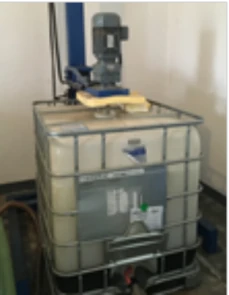
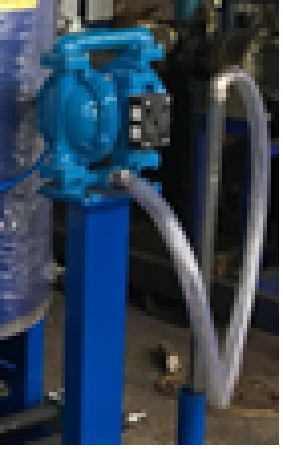
Material supply can include IBC polyol stirring, automatic diaphragm-pump refill and separately specified polyol nucleation. Tank capacities and the final color/head arrangement are defined in the approved equipment schedule.
Technical-Center Dual-Head Backfoaming and Sample System
This separate R&D reference serves a large instrument-panel sample duty and a small-part sample duty. It supports formulation development and small-batch prototyping; the 300 g/s large-head reference does not replace the 80–320 g/s range of the separate carrier package above.
| Configuration item | Technical-center reference | Condition and scope |
|---|---|---|
| التطبيق | Formulation development, material comparison, instrument-panel samples and small-part trials | A flexible R&D/sample system, not a fixed-takt continuous production line. |
| Large-head duty | Maximum 300 g/s for instrument-panel backfoaming | A selected head-duty reference; actual shot quantity and output are set for the material and mold. |
| Small-head duty | 80–150 g/s for small specimens | Separate from the large-head duty; the values are not combined into one simultaneous-output rating. |
| PU materials | A: polyol; B: modified MDI isocyanate; reference A:B mass ratio 100:35 | Selected formulation only. HMI ratio-setting capability does not establish compatibility throughout every setting. |
| أوعية المواد | Nominal 60 L jacketed component vessels | Confirm usable volume, headspace, material exchange and operating limits for each vessel. |
| التحكم في درجة حرارة المادة | Specified ±2 °C control requirement | Setpoints and measurement positions follow the material and the agreed trial conditions. |
| Mixing-pressure reference | 150 bar ±10 bar (15 MPa ±1 MPa) | High-pressure mixing reference; distinct from mold-cavity pressure, tank pressure and overpressure-protection limits. |
| Pressure build-up | Specified ≤8 s at the mixing-head measurement point | A response requirement, not the molding cycle. |
| Cantilever | 5 m articulated working arrangement for the small-part head; Z-axis balancer and movement locks | Review actual travel, working height, head access and collision protection against the layout. |
| Optional electric carrier | At least 60 metric tonnes-force clamping; upper/lower tool loading reference 1,500 kg each; upper tilt 80°, lower tilt 45° | Optional tooling package; check actual tool weight, mounting, deflection and mechanical safety support. |
| Carrier motion reference | Parallel closing ≤5 s; full open/close sequence ≤8 s | Motion timing is separate from reaction, cure, cleaning, loading and demolding. |
| Mold-temperature reference | 60–70 °C for the selected formulation | Mold thermal units are separately selected; the equipment setting range is not the formulation’s universal process window. |
| Small-mold support | Customer-supplied support/table and small molds | Interface development for that small-mold support is outside this reference scope. Define mounting and any control handshake separately. |
| Trial records | PLC/HMI recipes, shot ID, pressure/flow/time records, SQL database and configured USB/Ethernet export | Data fields and interfaces are agreed for the project; a reserved ERP interface is not a completed ERP integration. |
Metering Verification for the Technical-Center Reference
The brief specifies a shot-mass deviation target of ±3% for injection quantities above 100 g. Its flowmeter-body accuracy reference of 0.5% is a sensor specification, not the complete system’s dosing accuracy. A separate FAT procedure describes 20 simulated-fluid draws with a ±0.3% repeatability criterion. These refer to different quantities and test conditions; none is substituted for another or published as a measured acceptance result here.
Included Functions and Optional Interfaces
The core reference coordinates high-pressure metering, two head duties, the articulated small-part head arrangement, material conditioning and operating controls. An electric flip carrier, IBC or drum supply station, material nucleation, mold-temperature units and enclosed extraction are separately specified options. The customer supplies the small molds/support. The proposal identifies the actual included options, site utilities, lifting access, receiving-tool interfaces and authorized remote-support connections.
Explore Haifeng equipment or request the selected equipment specifications.
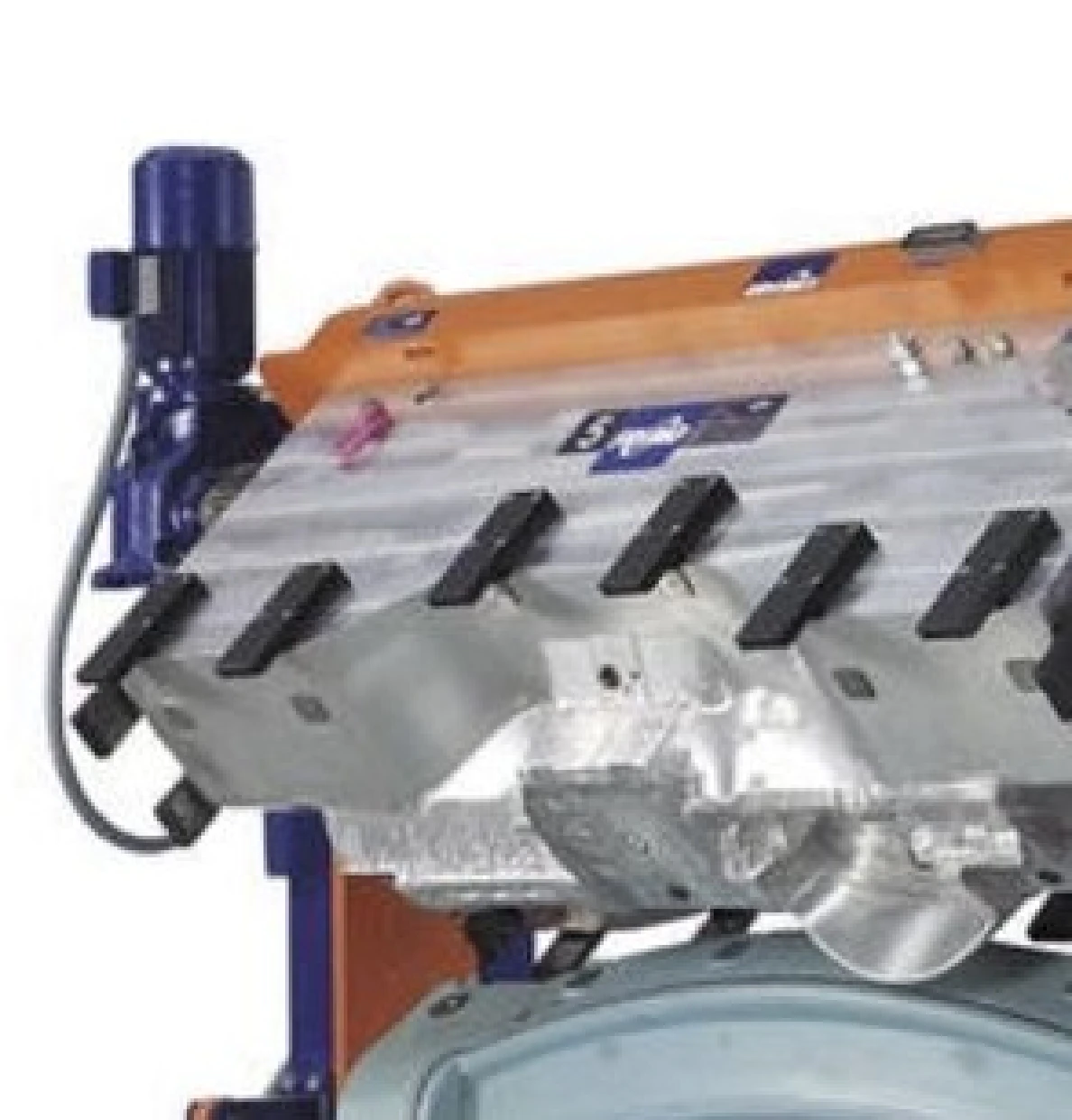
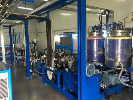
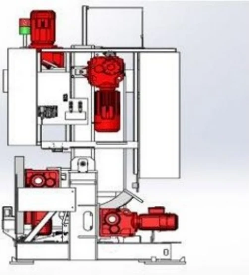
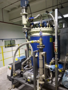
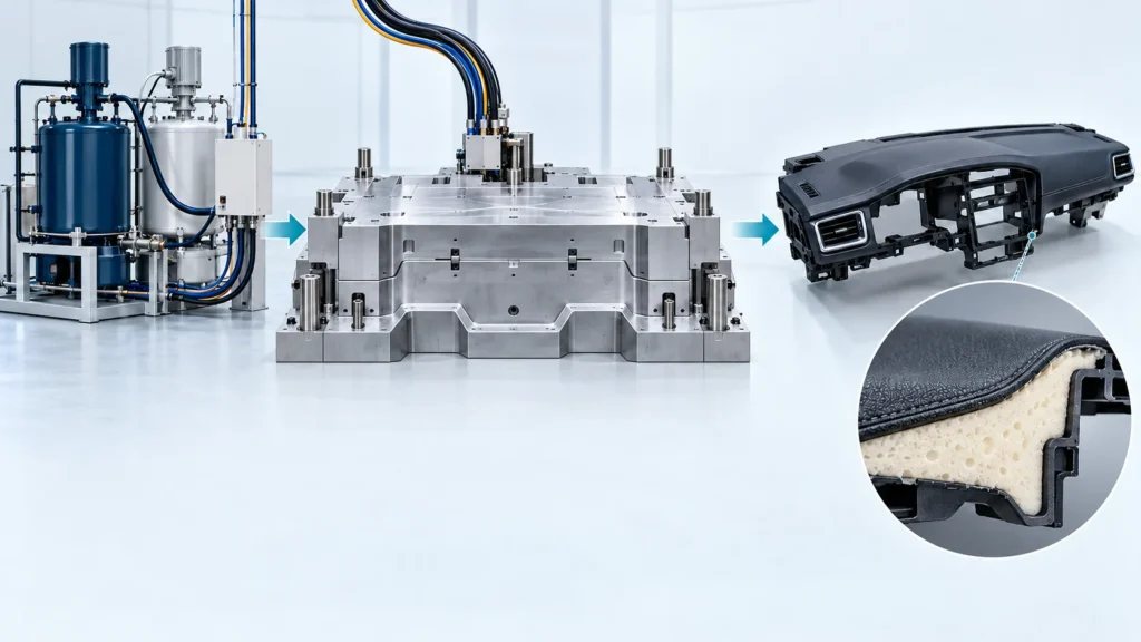
Dashboard Workcell — Technical Reference Illustrations
Equipment illustrations show the relevant process sections and configuration references.
المزايا الهندسية الرئيسية
For Automotive Dashboard PU Backfoaming Line, assess material compatibility, process control, equipment interfaces and changeover needs against your production brief.
Configured material delivery
Select the metering, head and temperature-control arrangement for the actual material, cavity and shot requirement.
Tooling and workflow flexibility
Coordinate carrier options, head access and customer-supplied sample tooling with the production or R&D workflow.
Traceable sample conditions
Record the selected recipe and shot parameters for comparative trials and process review.
Defined validation scope
Separate equipment tests from filling, adhesion, appearance, emissions and airbag-system qualification.
مشاريع ذات صلة
The dashboard project is an application reference; confirm the skin, backing, tooling and delivered modules before comparing results.
الأسئلة الشائعة
أسئلة هندسية وشرائية حول مسار إنتاج البولي يوريثان هذا.
Can this route serve both production and a technical center?
Why are different head-output ranges shown?
Is flowmeter accuracy the same as shot-weight repeatability?
Is the electric flip carrier included in every system?
Does the carrier movement time determine demolding time?
What production or trial data can be retained?
Does the backfoaming machine certify airbag deployment safety?
How are installation and remote support arranged?
ما المدخلات اللازمة لهذا التكوين؟
What differs between a dashboard production cell and a development configuration?
ناقش مشروع الإنتاج الخاص بك في قطاع السيارات
Share the following for this application: Skin and substrate drawings, PU data, shot range, open/closed-tool route, molds/carriers, existing equipment and trial or output requirements. Our team will reply within one business day. Once requirements are clear, we provide a preliminary proposal within two business days.


